CAN-bus was designed for automotive applications but is also used in other areas. The protocol was officially released in 1986 by the Society of Automotive Engineers (SAE). CAN become become most available OBD standard for vehicles produced after 2007 yrs.
A modern automobile may have up to 50 electronic control units (ECU) for various subsystems. Usually the biggest processor is the engine control unit, others are used for transmission, airbags, antilock braking, cruise control, audio systems, windows, doors, mirror adjustment, etc. Some of these form independent subsystems, but communications among others are essential. The CAN standard was devised to fill this need. CAN is a multi-master broadcast serial bus standard for connecting electronic control units (ECUs).
The CAN bus may be used in vehicles to connect engine control unit and transmission, or (on a different bus) to connect the door locks, climate control, seat control, etc. Today the CAN bus is also used as a fieldbus in general automation environments.
The devices that are connected by a CAN network are typically sensors, actuators and control devices. A CAN message never reaches these devices directly, but instead a host-processor and a CAN Controller is needed between these devices and the bus.
The CAN data link layer protocol is standardized in ISO 11898-1 (2003).
There are several CAN physical layer standards:
ISO 11898-1: CAN Data Link Layer and Physical Signalling
ISO 11898-2: CAN High-Speed Medium Access Unit (uses a two-wire balanced signaling scheme. It is the most used physical layer in car powertrain applications and industrial control networks)
ISO 11898-3: CAN Low-Speed, Fault-Tolerant, Medium-Dependent Interface
ISO 11898-4: CAN Time-Triggered Communication (standard defines the time-triggered communication on CAN (TTCAN). It is based on the CAN data link layer protocol providing a system clock for the scheduling of messages)
ISO 11898-5: CAN High-Speed Medium Access Unit with Low-Power Mode
ISO 11992-1: CAN fault-tolerant for truck/trailer communication
ISO 11783-2: 250 kbit/s, Agricultural Standard - uses four unshielded twisted wires; two for CAN and two for terminating bias circuit (TBC) power and ground. This bus is used on agricultural tractors. This bus is intended to provide interconnectivity with any implementation adhering to the standard.
SAE J1939-11: 250 kbit/s, Shielded Twisted Pair (STP) - standard uses a two-wire twisted pair, -11 has a shield around the pair while -15 does not. SAE 1939 is widely used in agricultural & construction equipment
SAE J1939-15: 250 kbit/s, UnShielded Twisted Pair (UTP) (reduced layer)
SAE J2411: Single-wire CAN (SWC)
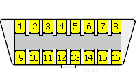
CAN-bus usually accessed via 6 and 14 pin of OBD II connector
OBD 2 CAN pinout
| Pin | Signal | Description |
| 4 | CGND | GND |
| 5 | SGND | GND |
| 6 | CAN High | |
| 14 | CAN Low | |
| 16 | +12v | Battery power |
Here are some schemes of OBD-II diagnostic cables
- OBD-II J1850 USB cable scheme
- OBD-2 ISO-9141-2, KWP2000 K-Line, L-Line RS-232 cable
- OBD-2 ISO 9141-2 (14230-4, KWP2000) simple RS-232 cable
- OBD-2 universal diagnostic serial cable scheme for ISO 15765-4 CAN, SAE J1850 PWM, SAE J1850 VPW, ISO 9141-2, ISO 14230-4 and SAE J1939


 правильная
 с ошибками