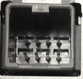
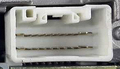
20 pin Main Audio Connector
Connector (20-pin,to white receptacle), harness connector view
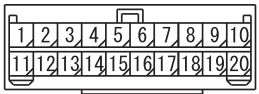
| Terminal No. | Signal symbol | Check item | Check condition | Terminal voltage |
| 1 | ACC | ACCESSORY (+) | Ignition switch: ACC position | System voltage (DC) |
| 2 | REM+ | REMOCON | Ignition switch: ACC position | 3.3V (DC) |
| 5 | RR+ | SPEAKER RR (+) | When the sound is output | 0 - System voltage (AC) |
| 6 | FR+ | SPEAKER FR (+) | When the sound is output | 0 - System voltage (AC) |
| 7 | RL+ | SPEAKER RL (+) | When the sound is output | 0 - System voltage (AC) |
| 8 | FL+ | SPEAKER FL (+) | When the sound is output | 0 - System voltage (AC) |
| 9 | ILL+ | ILLUMINATION (+) | Tail lamp switch: ON | System voltage (DC) |
| 10 | +B2 | BATTERY (+) | Always | System voltage (DC) |
| 11 | REED | VEHICLE SPEED PULSE | Ignition switch: ON | 0 - System voltage (pulse) |
| 12 | REM- | REMOCON GND | Always | 1 V or less |
| 14 | ANT+ | ANTENNA +B | Ignition switch: ACC position | System voltage (DC) |
| 15 | RR- | SPEAKER RR (-) | When the sound is output | 0 - System voltage (AC) |
| 16 | FR- | SPEAKER FR (-) | When the sound is output | 0 - System voltage (AC) |
| 17 | RL- | SPEAKER RL (-) | When the sound is output | 0 - System voltage (AC) |
| 18 | FL- | SPEAKER FL (-) | When the sound is output | 0 - System voltage (AC) |
| 20 | GND2 | POWER GND | Always | 1 V or less |
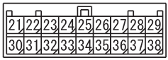
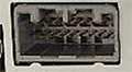
Connector (18-pin, to white), harness connector view
| Terminal No. | Signal symbol | Check item | Check condition | Terminal voltage |
|---|---|---|---|---|
| 21 | TVR | AUX/RSES INPUT RIGHT | When the sound is input from audio and video adapter/rear display unit | 1.2Vrms (AC) |
| 22 | TVL | AUX/RSES INPUT LEFT | When the sound is input from audio and video adapter/rear display unit | 1.2Vrms (AC) |
| 23 | NAVR | HFM/USB S-INPUT RIGHT | When the hands-free interface system/USB device operation | 1.2 Vrms (AC) |
| 24 | NAVL | HFM/USB S-INPUT LEFT | When the hands-free interface system/USB device operation | 1.2 Vrms (AC) |
| 28 | P-ON | IE-BUS POWER ON | Ignition switch: ACC position | 1 V or less |
| 29 | IEH | IE-BUS (+) | Ignition switch: ACC position | More than 120mV |
| 30 | TVG | AUX/RSES INPUT GND | Always | 1 V or less |
| 32 | NAVG | HFM/USB INPUT GND | When the hands-free interface system/USB device operation | 1.2 Vrms (AC) |
| 34 | MUTE | TEL MUTE | Ignition switch: ACC position | 1 V or less |
| 38 | IEL | IE-BUS (+) | Ignition switch: ACC position | More than 120mV |
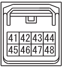
8 pin Camera Connector
| Terminal No. | Signal symbol | Check item | Check condition | Terminal voltage |
|---|---|---|---|---|
| 41 | CACC | VCC |
|
5.8 - 7.0V (DC) |
| 42 | CDET | CAMERA DETECT |
|
0 - 5V (DC) |
| 43 | REV | PS-R |
|
System voltage (DC) |
| 44 | +B | BATTERY (+) | Always | System voltage (DC) |
| 45 | CGND | GND | Always | 1 V or less |
| 46 | CMP+ | CAMERA SIGNAL |
|
1Vp-p (AC) |
| 47 | CMP- | SHIELD (CAMERA) | Always | 1 V or less |
| 48 | GND2 | GND | Always | 1 V or less |
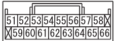
16 pin connector
| 54 | V-ON | VIDEO DETECT | Always | 1 V or less |
5 pin Connector (vehicles with multi around monitor)

| Terminal No. | Signal symbol | Check item | Check condition | Terminal voltage |
|---|---|---|---|---|
| 73 | OFSW | DISP OFF RQ |
|
1 V or less |
| 74 | CMSW | Camera SW Signal |
|
1 V or less |
| 75 | C-ON | DISP RQ |
|
1 V or less |
|
4 V or more |
 правильная
 с ошибками