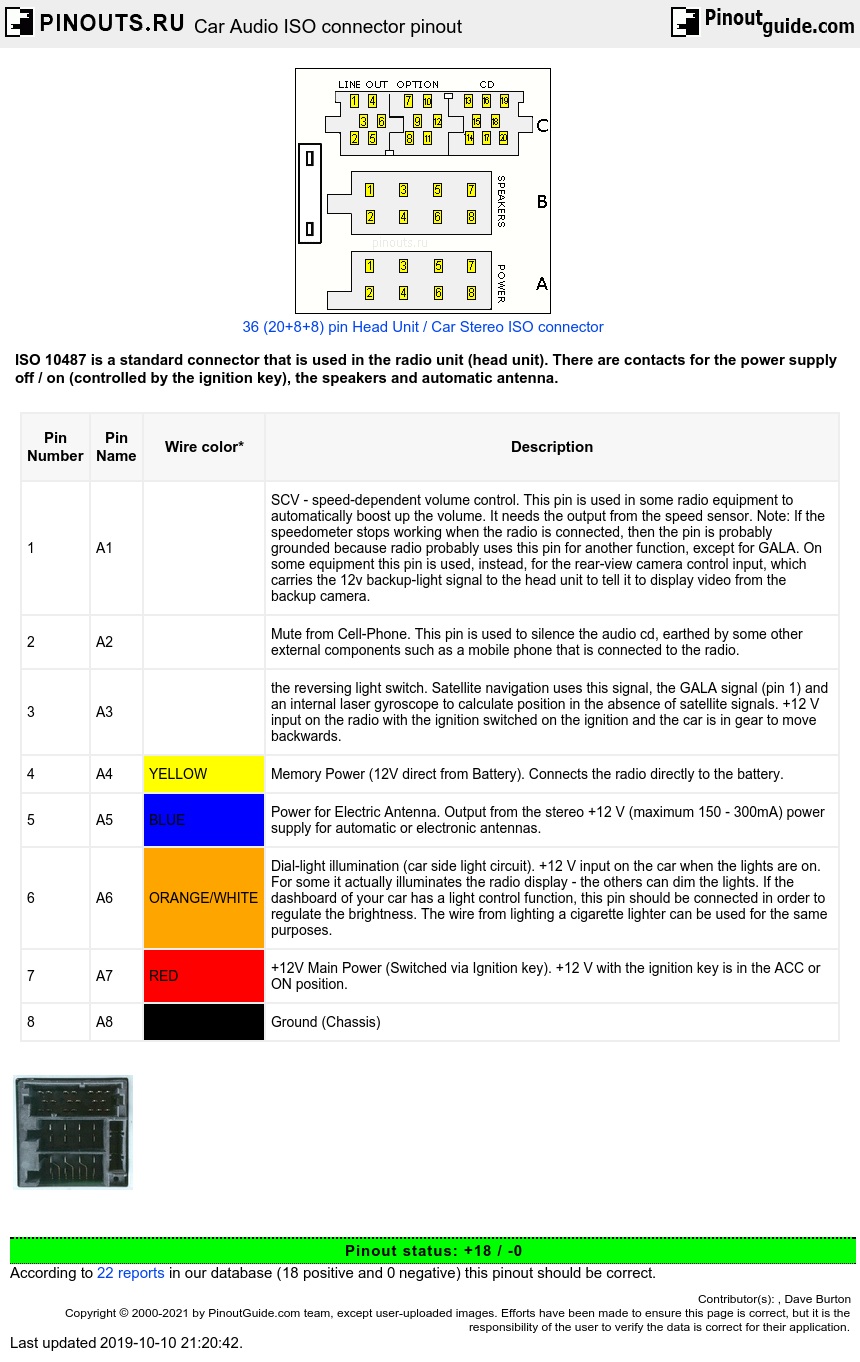
Car audio ISO connector A pinout
| Pin Number |
Pin Name |
Wire color* | Description |
|---|---|---|---|
| 1 | A1 | SCV - speed-dependent volume control. This pin is used in some radio equipment to automatically boost up the volume. It needs the output from the speed sensor. Note: If the speedometer stops working when the radio is connected, then the pin is probably grounded because radio probably uses this pin for another function, except for GALA. On some equipment this pin is used, instead, for the rear-view camera control input, which carries the 12v backup-light signal to the head unit to tell it to display video from the backup camera. | |
| 2 | A2 | Mute from Cell-Phone. This pin is used to silence the audio cd, earthed by some other external components such as a mobile phone that is connected to the radio. | |
| 3 | A3 | the reversing light switch. Satellite navigation uses this signal, the GALA signal (pin 1) and an internal laser gyroscope to calculate position in the absence of satellite signals. +12 V input on the radio with the ignition switched on the ignition and the car is in gear to move backwards. | |
| 4 | A4 | YELLOW | Memory Power (12V direct from Battery). Connects the radio directly to the battery. |
| 5 | A5 | BLUE | Power for Electric Antenna. Output from the stereo +12 V (maximum 150 - 300mA) power supply for automatic or electronic antennas. |
| 6 | A6 | ORANGE/WHITE | Dial-light illumination (car side light circuit). +12 V input on the car when the lights are on. For some it actually illuminates the radio display - the others can dim the lights. If the dashboard of your car has a light control function, this pin should be connected in order to regulate the brightness. The wire from lighting a cigarette lighter can be used for the same purposes. |
| 7 | A7 | RED | +12V Main Power (Switched via Ignition key). +12 V with the ignition key is in the ACC or ON position. |
| 8 | A8 | BLACK | Ground (Chassis) |
*Wire colors are typical and may be changed without notice.
a4 and a7 pins may be reversed (a4=acc switched, a7=batt fix) in some Head Units, i.e. sony japan . A7 and A4 must be connected to +12V to get radio power on.
Car audio ISO connector B pinout
Connector B is used only for the speakers. Which wire goes to which speaker can be easily determined with a battery of 1.5 V. Speaker will click and you will see the diaphragm move forward or backward. Speakers must be properly phased (note the + and - half on the speaker), because otherwise you will have weak bass. Wire with a stripe usually goes to + pole of speaker.
| Pin Number |
Pin Name |
Typical Wire Color |
Description |
|---|---|---|---|
| 1 | B1 | PURPLE | Right Rear speaker+ |
| 2 | B2 | PURPLE/BLACK | Right Rear speaker- |
| 3 | B3 | GRAY | Right Front speaker+ |
| 4 | B4 | GRAY/BLACK | Right Front speaker- |
| 5 | B5 | WHITE | Left Front speaker+ |
| 6 | B6 | WHITE/BLACK | Left Front speaker- |
| 7 | B7 | GREEN | Left Rear speaker+ |
| 8 | B8 | GREEN/BLACK | Left Rear speaker- |
Car audio ISO connector C pinout
Connector C are consist of 3 separate connectors that are tied together. It is not always present, sometimes only a part.
| Pin Number |
Pin Name |
Description |
|---|---|---|
| 1 | C1 | Line out left rear |
| 2 | C2 | Line out right rear |
| 3 | C3 | Line out ground |
| 4 | C4 | Line out front left |
| 5 | C5 | Line out front right |
| 6 | C6 | +12v switched - maximum 150mA |
| 7 | C7 | RXD |
| 8 | C8 | TXD |
| 9 | C9 | Chassis ground |
| 10 | C10 | +12v switched - maximum 150mA |
| 11 | C11 | Remote control in |
| 12 | C12 | Remote control ground |
| 13 | C13 | CDC data in (bus) |
| 14 | C14 | CDC data out |
| 15 | C15 | CDC +12v permanent |
| 16 | C16 | CDC +12v switched - maximum 300mA (+A) |
| 17 | C17 | CDC data ground (+U) |
| 18 | C18 | CDC audio frequency ground |
| 19 | C19 | CDC audio frequency left |
| 20 | C20 | CDC audio frequency right |
Warning! The connector wiring may vary depending on the car manufacturer!
Take special care when installing into ’98 or later VW/Audi/Skoda/Seat models as there may be a 12 V connection on Pin A5, which could damage the car stereo or into Ford from ’97 or later, with an ISO connector, on which damage to the car’s microcomputers is possible if misconnected.
 correct
 incorrect