Pinouts >  Various Electronic Devices  >  Arduino pinouts

unknown connector
The Arduino Ethernet is a microcontroller board based on the ATmega328. The Ethernet differs from other boards in that it does not have an onboard USB-to-serial driver chip, but has a Wiznet Ethernet interface. This is the same interface found on the Ethernet shield.

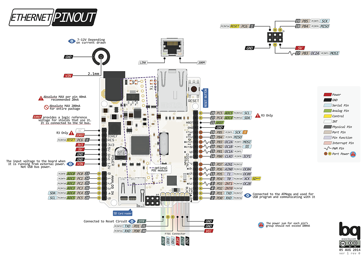
The Arduino Ethernet  has 14 digital input/output pins, 6 analog inputs, a 16 MHz crystal oscillator, a RJ45 connection, a power jack, an ICSP header, and a reset button.
NB: Pins 10, 11, 12 and 13 are reserved for interfacing with the Ethernet module and should not be used otherwise. This reduces the number of available pins to 9, with 4 available as PWM outputs.
An optional Power over Ethernet module can be added to the board as well.

There are no any reports for this pinout! You may rate this document by clicking the button below.

Is this pinout
Source(s) of this and additional information: http://www.pighixxx.com/test/portfolio-items/ethernet/?portfolioID=314
Copyright © 2000-2023 by pinouts.ru team, except user uploaded images.
No portion of this webpage may be reproduced in any form without visible link to pinouts.ru .
Efforts have been made to ensure this page is correct, but it is the responsibility of the user to verify the data is correct for their application.
Change privacy settings