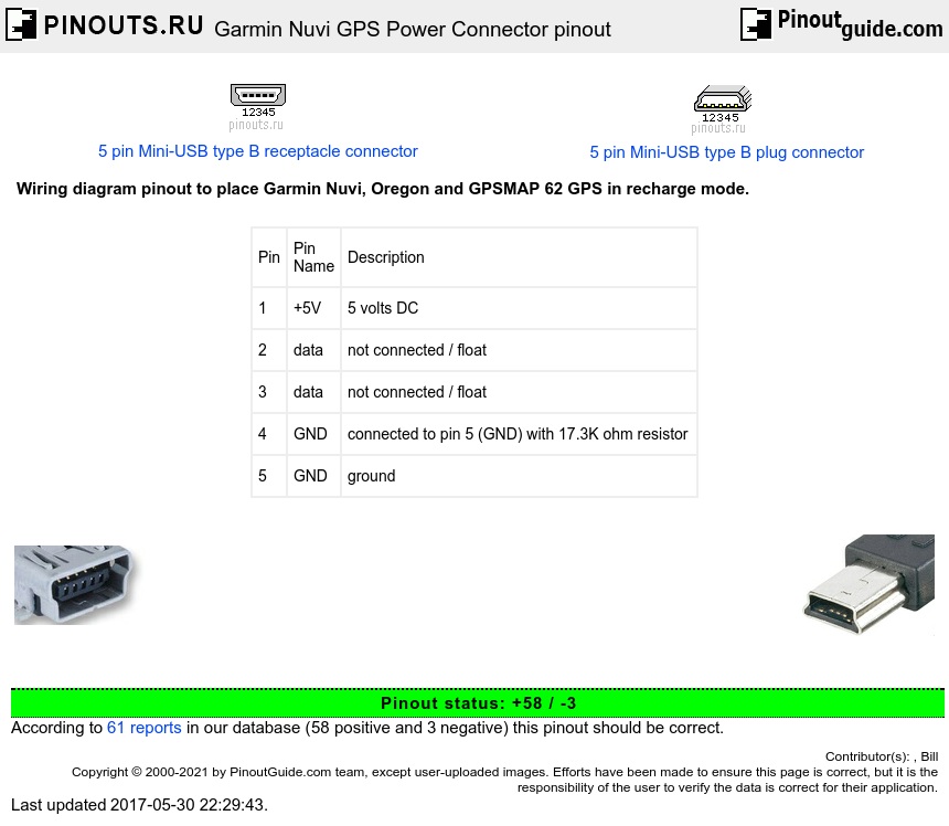
| Pin | Pin Name |
Description |
| 1 | +5V | 5 volts DC |
| 2 | data | not connected / float |
| 3 | data | not connected / float |
| 4 | GND | connected to pin 5 (GND) with 17.3K ohm resistor |
| 5 | GND | ground |
Standard 5 pin mini-USB connector has pin 4 connect to ground (pin 5) through a 200K ohm resistor (Note: The standard USB connector has only 4 pins, the mini-USB has 5 pins). To place Nuvi into charging mode, the 200K ohm resistor must be changed to 17.3K ohm. (also successful with 18k and 22K ohm resistor from Radio Shack, also a cheap 1/8W, 5%, 15k ohm resistor will work just fine!). Work with 22 k ohm for a Garmin Drive 60 too.
Nuvi behavior depends on mini-USB plug connection. (IMHO) it is like this:
pin 4 not connected - data cable, nuvi connects to PC as removable drive, navigation NOT possible.
pin 4 & 5 short-circuited - USB supply 500mA, possible navigation,
pin 4 & 5 connected through 18kOhm resistor - Garmin supply 1A, possible navigation.
pin 4 & 5 connected through 22kOhm resistor - Garmin supply 500mA, possible navigation.
I personally modified a cable that connected pin 4 to pin 5 (shorted), and verified the 500 mA charge behavior as noted above.
I simply waded up some aluminum foil and stuck it in the connector so that pins 4 and 5 were shorted. Works.
Nuvi requires 1000mA for simultaneous charging + GPS operation [many 'generic' 12VDC-to-USB adapters output a maximum 500mA]
Garmin Oregon requires a resistor of at least 47K ohm for running in external power supply mode (100K ohm also works). Smaller values are working, too, but Oregon then first shows a message that an unsupported accessory was found.
On Nuvi 670 add 18k resistor between pins 4 & 5 - and it doesn't go into mass storage mode.
On my Nuvi car cigarette adaptor, data pin 2 is shorted to pin 3. Not sure it makes any difference however. I confirmed a 17.5k resistor between 4 and 5.
GPSMAP 62:
pin 4 not connected - data cable, GPSMAP 62 connects to PC as removable drive.
If it fails because it is connected to your car battery, it switches to external power supply mode after several secondes.
pin 4 & 5 connected through 47 k Ohm resistor - GPSMAP 62 switches to external power supply mode immediately without waiting.
Comment:
I modified a Dezlcam's magnet mount assembly which allowed me to experiment with other home brew chargers - from this I have new info as I tested the GPS within dev mode showing the charging status. The GTM60 cable is a rated 5V/2A charger, between its pins 4/5 it has a 27.6 kOhm resistor (measured at 66 F). I sourced a 25 kOhm resistor from a scrap PCB and soldered it into the mag mount assembly, and my garmin DezlCam permits 2.5A charging rate thru the mini-USB connector now - before it would only charge with the GTM60 charger. Interestingly, I used the GTM60 in conjunction with this resistor mod and the GPS unit didn't care about the lower resistance and maintained the 2.5A charging rate(due to 27.6 kOhm being in parallel with my added 25 kOhm). The length and AWG size of the USB cable's wires makes a huge impact on voltage drop and the viability of using an alternate cable (quality 22AWG charging cable yielded 4.7V from my charger vs some thin crap which yields 4.2V). I found that the rear mini-USB currently allows a max of 2.5A draw and the 'front\ micro-USB (used for data xfers, etc) is good for 1.8A - both depending on the charger and the quality of cable built. Both of my standalone USB phone chargers (BackBerry and an Amazon) were able to put out 1.8A over a microusb connection. Attempting both phone chargers on the rear mini-usb connection yielded unhappy chargers because of the GPS wanting 2.5. So for those Garmin units that are compatible with the GTM60, owners may want to try a 25 kOhm resistor - and ensure they have the proper power supply to feed it. Going into the GPS's developer mode with the resistor mod intalled and viewing the power source menu item revealed the following steps of current.
Micro:
500mA
1300mA
1800mA
Mini
500 mAcontinuous
1300 mA
2500 mA **
** will trip weak DC power supplies

 correct
 incorrect