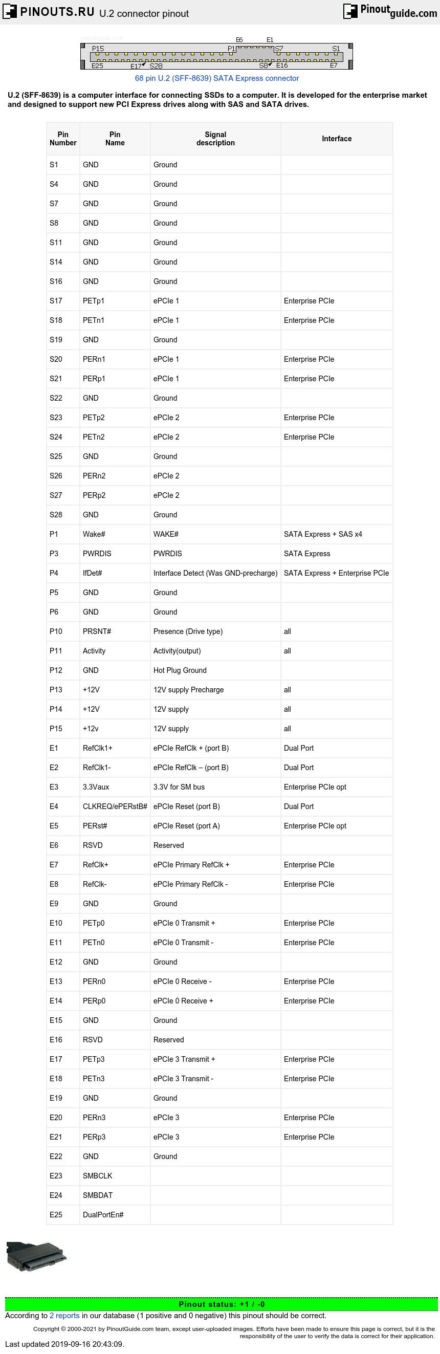
U.2 connector is a combination/ extension of the existing SATA and SAS connectors, which offer up to 4x PCIe 3.0 lanes to a connected device. The Enterprise SSD form factor was released on December 20, 2011 by SFFWG, as a mechanism for providing PCI Express connections to SSDs for the enterprise market. Goals included supporting existing 2.5 and 3.5 mechanical enclosures, to be hot swappable and to allow legacy SAS and SATA drives to be mixed using the same connector family.
The U.2 connector is mechanically identical to the SATA Express device plug, but provides four PCI Express lanes through a different usage of available pins. U.2 devices may be connected to an M.2 port using an adapter.
| Pin Number |
Pin Name |
Signal description |
Interface |
|---|---|---|---|
| S1 | GND | Ground | |
| S4 | GND | Ground | |
| S7 | GND | Ground | |
| S8 | GND | Ground | |
| S11 | GND | Ground | |
| S14 | GND | Ground | |
| S16 | GND | Ground | |
| S17 | PETp1 | ePCIe 1 | Enterprise PCIe |
| S18 | PETn1 | ePCIe 1 | Enterprise PCIe |
| S19 | GND | Ground | |
| S20 | PERn1 | ePCIe 1 | Enterprise PCIe |
| S21 | PERp1 | ePCIe 1 | Enterprise PCIe |
| S22 | GND | Ground | |
| S23 | PETp2 | ePCIe 2 | Enterprise PCIe |
| S24 | PETn2 | ePCIe 2 | Enterprise PCIe |
| S25 | GND | Ground | |
| S26 | PERn2 | ePCIe 2 | |
| S27 | PERp2 | ePCIe 2 | |
| S28 | GND | Ground | |
| P1 | Wake# | WAKE# | SATA Express + SAS x4 |
| P3 | PWRDIS | PWRDIS | SATA Express |
| P4 | IfDet# | Interface Detect (Was GND-precharge) | SATA Express + Enterprise PCIe |
| P5 | GND | Ground | |
| P6 | GND | Ground | |
| P10 | PRSNT# | Presence (Drive type) | all |
| P11 | Activity | Activity(output) | all |
| P12 | GND | Hot Plug Ground | |
| P13 | +12V | 12V supply Precharge | all |
| P14 | +12V | 12V supply | all |
| P15 | +12v | 12V supply | all |
| E1 | RefClk1+ | ePCIe RefClk + (port B) | Dual Port |
| E2 | RefClk1- | ePCIe RefClk – (port B) | Dual Port |
| E3 | 3.3Vaux | 3.3V for SM bus | Enterprise PCIe opt |
| E4 | CLKREQ/ePERstB# | ePCIe Reset (port B) | Dual Port |
| E5 | PERst# | ePCIe Reset (port A) | Enterprise PCIe opt |
| E6 | RSVD | Reserved | |
| E7 | RefClk+ | ePCIe Primary RefClk + | Enterprise PCIe |
| E8 | RefClk- | ePCIe Primary RefClk - | Enterprise PCIe |
| E9 | GND | Ground | |
| E10 | PETp0 | ePCIe 0 Transmit + | Enterprise PCIe |
| E11 | PETn0 | ePCIe 0 Transmit - | Enterprise PCIe |
| E12 | GND | Ground | |
| E13 | PERn0 | ePCIe 0 Receive - | Enterprise PCIe |
| E14 | PERp0 | ePCIe 0 Receive + | Enterprise PCIe |
| E15 | GND | Ground | |
| E16 | RSVD | Reserved | |
| E17 | PETp3 | ePCIe 3 Transmit + | Enterprise PCIe |
| E18 | PETn3 | ePCIe 3 Transmit - | Enterprise PCIe |
| E19 | GND | Ground | |
| E20 | PERn3 | ePCIe 3 | Enterprise PCIe |
| E21 | PERp3 | ePCIe 3 | Enterprise PCIe |
| E22 | GND | Ground | |
| E23 | SMBCLK | ||
| E24 | SMBDAT | ||
| E25 | DualPortEn# |
PCIe names the signals on the device from the host perspective i.e. for PCIe products, a receiver on the device has a transmitter signal name.
The PETpx and PETnx pins shall be connected to the PCI Express Receiver differential pair on the SATA Express device or PCIe module. The PERpx and PERnx pins shall be connected to the PCI Express Transmitter differential pair on the SATA Express device or PCIe module.
 correct
 incorrect