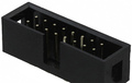
| Pin Number |
Pin Name |
Description |
|---|---|---|
| 1 | No Connection | No Connection |
| 2 | VCC - USB | Dual USB Pins #1 / #2 |
| 3 | VCC - USB | Dual USB Pins #1 / #2 |
| 4 | VCC - USB | Dual USB Pins #1 / #2 |
| 5 | HDD and ESUP LED + | To R19, Then CTRL Panel Pin #6 To R20, Then CTRL Panel Pin #14 |
| 6 | No Connection | No Connection |
| 7 | No Connection | No Connection |
| 8 | No Connection | No Connection |
| 9 | Ground | CTRL Panel Pins #3 / #7 / #15 / #16 |
| 10 | Ground if CTRL Panel is connected | CTRL Panel Pin # 11 |
| 11 | Ground | Dual USB Pins #7 / #8 |
| 12 | USB #1 - Data - | Dual USB Pin #3 |
| 13 | USB #1 - Data + | Dual USB Pin #5 |
| 14 |
Ground |
Dual USB Pins #7 / #8 |
| 15 | No Connection | No Connection |
| 16 | Ground | Dual USB Pins #7 / #8 |
| 17 | USB #2 - Data - | Dual USB Pin #4 |
| 18 | USB #2 - Data + | Dual USB Pin #6 |
| 19 | Ground | Dual USB Pins #7 / #8 |
| 20 | Power Switch | CTRL Panel Pin #2 |
| 21 | Pin Removed - KEY | No Connection |
| 22 | HDD LED - | CTRL Panel Pin #4 |
| 23 | Power LED + (Green / On) | CTRL Panel Pin #5 |
| 24 | ESUP LED - | CTRL Panel Pin #13 |
| 25 | Ground | CTRL Panel Pins #3 / #7 / #15 / #16 |
| 26 | No Connection | No Connection |
| 27 | Power LED + (Yellow / Off) | CTRL Panel Pin #9 |
| 28 | Suspend Switch | CTRL Panel Pin #8 |
| 29 | Intruder Pin #2 | Intruder Pin #2 |
| 30 | Intruder Pin #1 | Intruder Pin #1 |
| 31 | External Speaker Pin #2 | External Speaker Pin #2 |
| 32 | Intruder Pin #3 | Intruder Pin #3 |
| 33 | External Speaker Pin #4 / #5 | External Speaker Pin #4 / #5 |
| 34 | External Speaker Pin #1 | External Speaker Pin #1 |
Note 1. The power LED is a 'bi-colour' type'. The voltage on the control pair is reversed to switch from one colour to the other (so +5v / 0v is Yellow, 0v / +5v is Green
Note 2. The USB 5v fuses are on the motheboard (replacing the front panel board won't fix a blown fuse)
 correct
 incorrect