| APC Pin | USB Pin | Description |
|---|---|---|
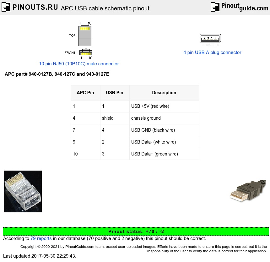
| 1 | 1 | USB +5V (red wire) |
| 4 | shield | chassis ground |
| 7 | 4 | USB GND (black wire) |
| 9 | 2 | USB Data- (white wire) |
| 10 | 3 | USB Data+ (green wire) |
Full pinout from APC Back-UPS CS 500 manual
| UPS Pin |
UPS signal | Description |
|---|---|---|
| 1 | USB_VCC | decoupled with a ferrite, and protected with a 6.2V zener on the PCB side |
| 2 | ON_BATT | (active high) - Logic 1: 12V via 3kohm resistor, Logic 0: 0V via open collector of 2N2222 to gound |
| 3 | \Lo_BATT | (active low) - Logic 1: 12V via 3kohm resistor, Logic 0: 0V via open collector of 2N2222 to gound |
| 4 | GND | direct connection, no decoupling |
| 5,6 | USB TST (NC) | No physical connection |
| 7 | GND | decoupling via ferrite |
| 8 | INVSD | Active high to base of a 2N2222 (resistor input -> base: 3kohms, resistor base -> gnd: 1kohms) |
| 9 | USB Data- (negative) | Protected with 47ohms resistors, ferrite |
| 10 | USB Data+ (positive) | Protected with 47ohms resistors, ferrite |
AP9827 cable for CS500
------------

RJxx end (looking AGAINST the connector,numbering reversed):
   ------
  |    --  1 - green - USB 3 - USB+
  |    --  2 - white - USB 2 - USB-
  |    --  3
 _|    --  4 - black - usb 4 - GND
| |    --  5
|_|    --  6
  |    --  7 - brown - shield
  |    --  8
  |    --  9
  |    --  10 - red - usb 1 - +5V
   ------

USB end (looking against the connector):
 -----
|   | |
|  X| |  1 - red - +5V
|   | |
|  X| |  2 - white - USB-
|   | |
|  X| |  3 - green - USB+
|   | |
|  X| |  4 - black - GND
|   | |
 -----  shield - brown - SHIELD
Comment:
If you have an 8P8C (RJ45) plug, solder two jumper wires on the UPS side:
1) Pin 1 to Pin 5
2) Pin 10 to Pin 6.
You can then create a cable by replacing the end of an old USB cable with the correctly crimped RJ45 connector. No extra parts needed.
 correct
 incorrect