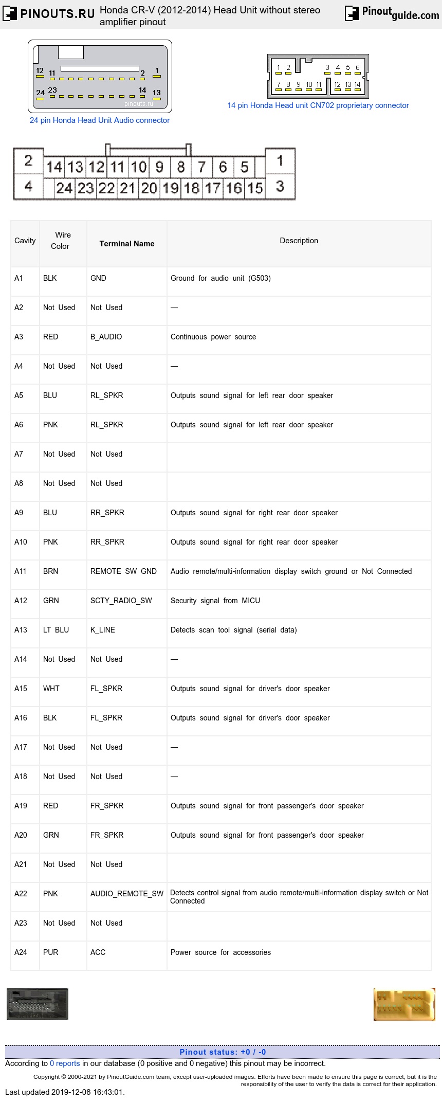
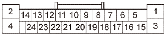
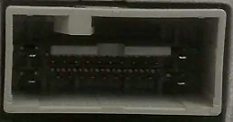
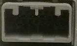
24 pin Audio-Navigation Unit Main Connector
|
Cavity |
Wire Color |
Terminal Name |
Description |
|---|---|---|---|
|
A1 |
BLK |
GND |
Ground for audio unit (G503) |
|
A2 |
Not Used |
Not Used |
— |
|
A3 |
RED |
B_AUDIO |
Continuous power source |
|
A4 |
Not Used |
Not Used |
— |
|
A5 |
BLU |
RL_SPKR |
Outputs sound signal for left rear door speaker |
|
A6 |
PNK |
RL_SPKR |
Outputs sound signal for left rear door speaker |
|
A7 |
Not Used |
Not Used |
|
|
A8 |
Not Used |
Not Used |
|
|
A9 |
BLU |
RR_SPKR |
Outputs sound signal for right rear door speaker |
|
A10 |
PNK |
RR_SPKR |
Outputs sound signal for right rear door speaker |
|
A11 |
BRN |
REMOTE SW GND |
Audio remote/multi-information display switch ground or Not Connected |
|
A12 |
GRN |
SCTY_RADIO_SW |
Security signal from MICU |
|
A13 |
LT BLU |
K_LINE |
Detects scan tool signal (serial data) |
|
A14 |
Not Used |
Not Used |
— |
|
A15 |
WHT |
FL_SPKR |
Outputs sound signal for driver's door speaker |
|
A16 |
BLK |
FL_SPKR |
Outputs sound signal for driver's door speaker |
|
A17 |
Not Used |
Not Used |
— |
|
A18 |
Not Used |
Not Used |
— |
|
A19 |
RED |
FR_SPKR |
Outputs sound signal for front passenger's door speaker |
|
A20 |
GRN |
FR_SPKR |
Outputs sound signal for front passenger's door speaker |
|
A21 |
Not Used |
Not Used |
|
|
A22 |
PNK |
AUDIO_REMOTE_SW |
Detects control signal from audio remote/multi-information display switch or Not Connected |
|
A23 |
Not Used |
Not Used |
|
|
A24 |
PUR |
ACC |
Power source for accessories |
A11,A22 are for multi-information display unit or center display unit.
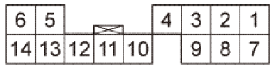
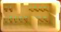
14 pin Audio-Navigation Unit CD-changer Connector
|
Cavity Wire Color Terminal Name |
Description |
||
|
C1 |
RED |
GA_AUDIO_L |
Inputs sound signal from GA-Net related units |
|
C2 |
GRN |
GA_AUDIO_R |
Inputs sound signal from GA-Net related units |
|
C3 |
GRY |
SH_GA_AUDIO |
Shield for terminals No. 1, No. 2, No. 7, and No. 8 |
|
C4 |
GRY |
SH_GA_BUS |
Shield for terminals No. 11 and No. 12 |
|
C5 |
PNK |
GA_SYS_ON |
Outputs signal for GA-Net related unit(s) switching ON/OFF |
|
C6 |
RED |
GA+B |
Power source for XM receiver and HandsFreeLink control unit |
|
C7 |
WHT |
GA_AUDIO_L |
Inputs sound signal from GA-Net related units |
|
C8 |
BLK |
GA_AUDIO_R |
Inputs sound signal from GA-Net related units |
|
C9 |
Not Used |
Not Used |
— |
|
C10 |
BLK |
GA GND |
Ground for XM receiver and HandsFreeLink control unit |
|
C11 |
PNK |
GA_BUS |
GA-Net bus communication signal |
|
C12 |
BLU |
GA_BUS |
GA-Net bus communication signal |
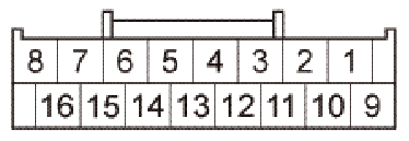
16 pin Audio-Navigation Unit Connector E
|
Cavity |
Wire Color |
Terminal Name |
Description |
|
B1 |
GRY |
SH_TELEM_SIG |
Shield for terminals No. 2 and No. 12 |
|
B2 |
YEL |
TELEM_SIG |
Inputs telephone sound signal from HandsFreeLink control unit |
|
B3 |
BLU |
B_CAN-L |
Communication signal |
|
B4 |
RED |
DUET_RX |
Communication signal to multi-information display unit |
|
B5 |
GRN |
DUET_TX |
Communication signal to multi-information display unit |
|
B6 |
LT GRN |
AUX_GND |
Ground for auxiliary jack assembly |
|
B7 |
GRY |
SH_AUX |
Shield for terminals No. 8, No. 17, and No. 18 |
|
B8 |
BLK |
AUX_SGND |
Ground for sound signal from auxiliary jack assembly |
|
B9 |
BLU |
COMPASS_TX |
Communication signal to electrical compass unit |
|
B10 |
GRY |
COMPASSTX |
Communication signal to electrical compass unit |
|
B12 |
BRN |
TELEM SIGO |
Inputs telephone sound signal from HandsFreeLink control unit |
|
B13 |
PNK |
B_CAN-H |
Communication signal |
|
B14 |
LT GRN |
DUET_CONT |
DUET control signal |
| B15 | GRY |
SH_DUET |
Shield for terminals No. 4 and No. 5 |
|
B16 |
LT BLU |
AUX_DET |
Detects connection signal for auxiliary jack assembly |
|
B17 |
RED |
AUX_R_CH |
Inputs sound signal from auxiliary jack assembly |
|
B18 |
WHT |
AUX_L_CH |
Inputs sound signal from auxiliary jack assembly |
|
B19 |
GRN |
COMPASS_RX |
Communication signal to electrical compass unit |
|
B20 |
PNK |
COMPASS_RX |
Communication signal to electrical compass unit |
|
Cavity |
Wire Color |
Terminal Name |
Description |
|
B1 |
GRY |
SH_TELEM_SIG |
Shield for terminals No. 2 and No. 12 |
|
B2 |
YEL |
TELEM SIGD |
Inputs telephone sound signal from HandsFreeLink control unit |
|
B3 |
BLU |
B_CAN-L |
Communication signal |
|
B4 |
RED |
DUET_RX |
Communication signal to center display unit |
|
B5 |
GRN |
DU ET_TX |
Communication signal to center display unit |
|
B6 |
LT GRN |
AUX_GND |
Ground for auxiliary jack assembly |
|
B7 |
GRY |
SH_AUX |
Shield for terminals No. 8, No. 17, and No. 18 |
|
B8 |
BLK |
AUX_SGND |
Ground for sound signal from auxiliary jack assembly |
|
B12 |
BRN |
TELEM SIGO |
Inputs telephone sound signal from HandsFreeLink control unit |
|
B13 |
PNK |
B_CAN-H |
Communication signal |
|
B14 |
LT GRN |
DUET_CONT |
DUET control signal |
|
B15 |
GRY |
SH_DUET |
Shield for terminals No. 4 and No. 5 |
|
B16 |
LT BLU |
AUX_DET |
Detects connection signal for auxiliary jack assembly |
|
B17 |
RED |
AUX_R_CH |
Inputs sound signal from auxiliary jack assembly |
|
B18 |
WHT |
AUX_L_CH |
Inputs sound signal from auxiliary jack assembly |
B1, B2, B12 are for HandsFree Unit
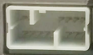
7 Pin USB Connector

|
Cavity |
Wire Color | Terminal Name |
Description |
|
H1 |
|
USB GND |
Ground for communication signal |
|
H2 |
— |
USB_DATA❑ |
Communication signal |
|
H3 |
— |
USB_DATA❑ |
Communication signal |
|
H4 |
— |
USB_VBUS |
Outputs power source for USB device |
|
H5 |
— |
USB SH |
Shield for terminals No. 1, No. 2, No. 3, and No. 4 |
|
H6 |
— |
USB ADPT |
Ground for connection signal |
|
H7 |
— |
USB ON |
Detects connection signal |
 correct
 incorrect