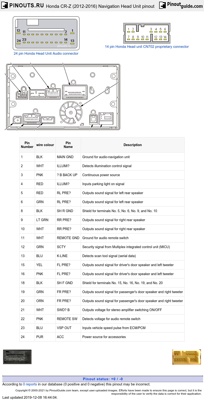
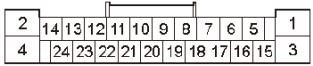
| Pin Number |
wire colour | Pin Name |
Description |
|---|---|---|---|
| 1 | BLK | MAIN GND | Ground for audio-navigation unit |
| 2 | WHT | ILLUMI- | Detects illumination control signal |
| 3 | PNK | + B BACK UP | Continuous power source |
| 4 | RED | ILLUMI+ | Inputs parking light on signal |
| 5 | RED | RL PRE+ | Outputs sound signal for left rear speaker |
| 6 | GRN | RL PRE- | Outputs sound signal for left rear speaker |
| 8 | BLK | SH R GND | Shield for terminals No. 5, No. 6, No. 9, and No. 10 |
| 9 | LT GRN | RR PRE+ | Outputs sound signal for right rear speaker |
| 10 | WHT | RR PRE- | Outputs sound signal for right rear speaker |
| 11 | WHT | REMOTE GND | Ground for audio remote switch |
| 12 | GRN | SCTY | Security signal from Multiplex integrated control unit (MICU) |
| 13 | BLU | K-LINE | Detects scan tool signal (serial data) |
| 15 | YEL | FL PRE+ | Outputs sound signal for driver's door speaker and left tweeter |
| 16 | PNK | FL PRE- | Outputs sound signal for driver's door speaker and left tweeter |
| 18 | BLK | SH F GND | Shield for terminals No. 15, No. 16, No. 19, and No. 20 |
| 19 | GRN | FR PRE+ | Outputs sound signal for passenger's door speaker and right tweeter |
| 20 | ORN | FR PRE- | Outputs sound signal for passenger's door speaker and right tweeter |
| 21 | WHT | SWD+ B | Outputs voltage for stereo amplifier switching ON/OFF |
| 22 | PNK | REMOTE SW | Detects voltage for audio remote switch |
| 23 | BLU | VSP OUT | Inputs vehicle speed pulse from ECM/PCM |
| 24 | PUR | ACC | Power source for accessories |
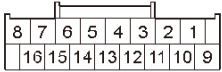
| Pin Number |
wire colour | Pin Name |
Description |
|---|---|---|---|
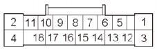
| 2 | BLK | SH SUBW GND | Shield for terminals No. 3 and No. 11 |
| 3 | RED | SUBW PRE+ | Outputs sound signal for subwoofer |
| 4 | GRY | TELM SIG SH | Shield for terminals No. 5 and No. 13 |
| 5 | GRN | TELM SIG + | Inputs sound signal for HFL |
| 6 | ORN | AUX RCH | Inputs sound signal from auxiliary jack assembly |
| 7 | BRN | AUX S GND | Ground for sound signal from auxiliary jack assembly |
| 8 | YEL | AUX LCH | Inputs sound signal from auxiliary jack assembly |
| 11 | WHT | SUBW PRE- | Outputs sound signal for subwoofer |
| 12 | LT BLU | AMP MUTE | Outputs stereo amplifier mute signal |
| 13 | RED | TELM SIG - | Inputs sound signal for HFL |
| 14 | GRY | AUX SH GND | Shield for terminals No. 6, No. 7, and No. 8 |
| 15 | WHT | AUX GND | Ground for auxiliary jack assembly |
| 16 | PUR | AUX DET | Detects connection signal for auxiliary jack assembly |
14 pin CD Changer
| Pin Number |
wire colour | Pin Name |
Description |
|---|---|---|---|
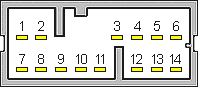
| 1 | WHT | GA AUDIO L+ | Inputs sound signal for GA audio left channel |
| 2 | BLK | GA AUDIO R+ | Inputs sound signal for GA audio right channel |
| 3 | GRY | GA AUDIO SH | Shield for terminals No. 1, No. 2, No. 7, and No. 8 |
| 4 | GRY | GA BUS SH | Shield for terminals No. 11 and No. 12 |
| 5 | BLU | GA SYS ON | GA audio control signal |
| 6 | ORN | GA + B | Power source for GA audio |
| 7 | GRN | GA AUDIO L- | Inputs sound signal for GA audio left channel |
| 8 | RED | GA AUDIO R- | Inputs sound signal for GA audio right channel |
| 10 | BLK | GA GND | Ground for GA audio |
| 11 | BRN | GA BUS- | Communication signal for GA audio |
| 12 | YEL | GA BUS+ | Communication signal for GA audio |
| Pin Number |
Pin Name |
Description |
|---|---|---|
| 1 | USB GND | Ground for communication signal |
| 2 | USB DATA+ | Communication signal |
| 3 | USB DATA- | Communication signal |
| 4 | USB VBUS | Outputs power source for USB device |
| 5 | USB SH | Shield for terminals No. 1, No. 2, No. 3, and No. 4 |
| 6 | USB DET | Detects connection signal |
| 7 | USB DET GND | Ground for connection signal |
External amplifier

| Pin Number |
wire colour | Pin Name |
Description |
|---|---|---|---|
| 5 | WHT | SUBW PRE- | Inputs sound signal for subwoofer |
| 6 | WHT | RR PRE- | Inputs sound signal for right rear speaker |
| 8 | ORN | FR PRE- | Inputs sound signal for passenger's door speaker and right tweeter |
| 9 | GRN | RL PRE- | Inputs sound signal for left rear speaker |
| 11 | PNK | FL PRE- | Inputs sound signal for driver's door speaker and left tweeter |
| 13 | WHT | SWD+ B | Inputs voltage for stereo amplifier switching ON/OFF |
| 17 | RED | SUBW PRE+ | Inputs sound signal for subwoofer |
| 18 | LT GRN | RR PRE+ | Inputs sound signal for right rear speaker |
| 20 | GRN | FR PRE+ | Inputs sound signal for passenger's door speaker and right tweeter |
| 21 | RED | RL PRE+ | Inputs sound signal for left rear speaker |
| 23 | YEL | FL PRE+ | Inputs sound signal for driver's door speaker and left tweeter |
| 24 | LT BLU | AMP MUTE | Inputs stereo amplifier mute signal |
| Pin Number |
wire colour | Pin Name |
Description |
|---|---|---|---|
| 1 | BLK | GND | Ground for audio unit (G502) |
| 2 | LT BLU | SUBW SP- | Outputs sound signal for subwoofer |
| 3 | WHT | + B | Continuous power source |
| 4 | RED | SUBW SP+ | Outputs sound signal for subwoofer |
| 5 | GRY | FL TW SP- | Outputs sound signal for left tweeter |
| 6 | GRY | FL SP- | Outputs sound signal for driver's door speaker |
| 7 | RED | FR SP- | Outputs sound signal for passenger's door speaker |
| 8 | RED | FR TW SP- | Outputs sound signal for right tweeter |
| 9 | BRN | RL SP- | Outputs sound signal for left rear speaker |
| 10 | ORN | RR SP- | Outputs sound signal for right rear speaker |
| 12 | LT BLU | FL TW SP+ | Outputs sound signal for left tweeter |
| 13 | WHT | FL SP+ | Outputs sound signal for driver's door speaker |
| 14 | BLU | FR SP+ | Outputs sound signal for passenger's door speaker |
| 15 | BLU | FR TW SP+ | Outputs sound signal for right tweeter |
| 16 | GRY | RL SP+ | Outputs sound signal for left rear speaker |
| 17 | BLU | RR SP+ | Outputs sound signal for right rear speaker |
 correct
 incorrect