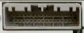
Without Stereo Amplifier
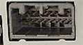
All connectors are wire side of female terminals.
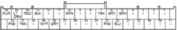
| Pin Number |
Pin Name |
Description |
|---|---|---|
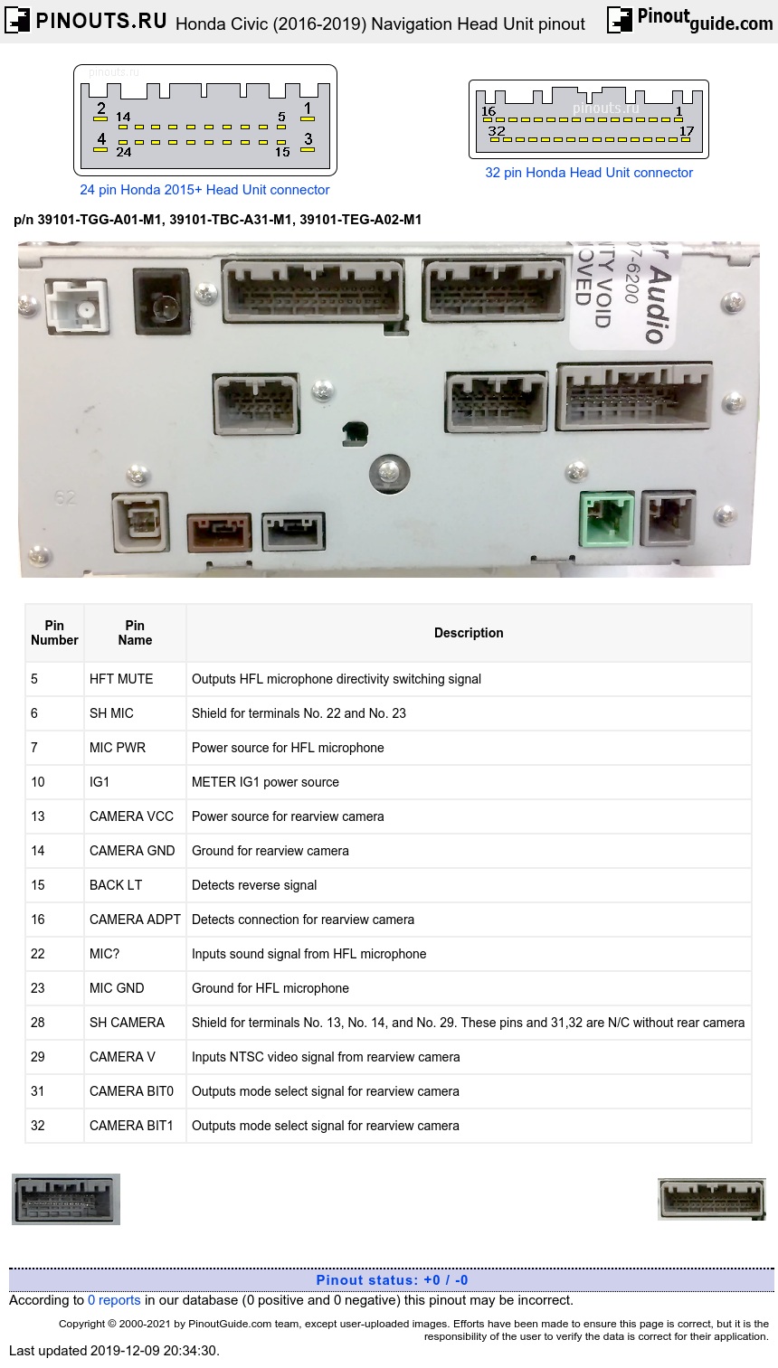
| 5 | HFT MUTE | Outputs HFL microphone directivity switching signal |
| 6 | SH MIC | Shield for terminals No. 22 and No. 23 |
| 7 | MIC PWR | Power source for HFL microphone |
| 10 | IG1 | METER IG1 power source |
| 13 | CAMERA VCC | Power source for rearview camera |
| 14 | CAMERA GND | Ground for rearview camera |
| 15 | BACK LT | Detects reverse signal |
| 16 | CAMERA ADPT | Detects connection for rearview camera |
| 22 | MIC+ | Inputs sound signal from HFL microphone |
| 23 | MIC GND | Ground for HFL microphone |
| 28 | SH CAMERA | Shield for terminals No. 13, No. 14, and No. 29. These pins and 31,32 are N/C without rear camera |
| 29 | CAMERA V | Inputs NTSC video signal from rearview camera |
| 31 | CAMERA BIT0 | Outputs mode select signal for rearview camera |
| 32 | CAMERA BIT1 | Outputs mode select signal for rearview camera |
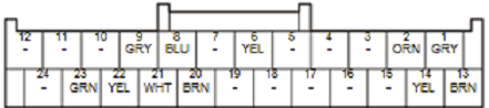

| Pin Number |
Pin Name |
Description |
|---|---|---|
| 1 | AUX NAVI SH | Shield for terminals No. 2, No. 13, and No. 14 |
| 2 | AUX BEEP | Outputs system beep signal |
| 6 | LANEWATCH SW | Detects LaneWatch on/off signal from LaneWatch switch |
| 8 | LWC CAM VCC | Power source for LaneWatch camera |
| 9 | SH LWC CAM | Shield for terminals No. 8, No. 20, No. 21, No. 22, and No. 23. All these pins are N/C if no LaneWatch |
| 13 | AUX NAVI | Outputs sound signal for voice guidance and Voice Recognition (VR) prompts |
| 14 | AUX NAVI GND | Basis ground for terminals No. 2 and No. 13. These pins are N/c if no Stereo Amplifier |
| 20 | LWC CAM VID | Inputs video signal from LaneWatch camera |
| 21 | LWC CAM VGND | Ground for LaneWatch camera |
| 22 | UNIT TO LWC | Communication signal for LaneWatch camera |
| 23 | LWC TO UNIT | Communication signal for LaneWatch camera |
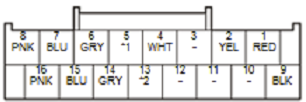
| Pin Number |
Pin Name |
Description |
|---|---|---|
| 1 | TUNER 6V | Power source for tuner unit |
| 2 | TUNER 9V | Power source for tuner unit |
| 4 | DISP CONT | Outputs signal for center display unit switching on/off |
| 5 | F-CAN B_H (with CMBS) F-CAN_H (w/o CMBS) |
Communication signal |
| 6 | AMP RS485 SH | Shield for terminals No. 7 and No. 8. These pins are N/c w/o Amplifier |
| 7 | RS485+ | Communication signal for stereo amplifier |
| 8 | RS485- | Communication signal for stereo amplifier |
| 9 | TUNER GND | Ground for tuner unit |
| 13 | F-CAN B_L (with CMBS) F-CAN_L (w/o CMBS) |
Communication signal |
| 14 | TUNER RS485 SH | Shield for terminals No. 15 and No. 16 |
| 15 | TUNER RS485+ | Communication signal for tuner unit |
| 16 | TUNER RS485- | Communication signal for tuner unit |

Without External Stereo Amplifier
| Pin Number |
Pin Name |
Description |
|---|---|---|
| 1 | GND | Ground for audio unit |
| 3 | +B AUDIO | Continuous power source |
| 5 | RL SPKR+ | Outputs sound signal for left rear speaker and left rear tweeter |
| 6 | RL SPKR- | Outputs sound signal for left rear speaker and left rear tweeter |
| 7 | RR SPKR+ | Outputs sound signal for right rear speaker and right rear tweeter |
| 8 | RR SPKR- | Outputs sound signal for right rear speaker and right rear tweeter |
| 12 | K LINE | Detects scan tool signal (serial data) |
| 14 | B-CAN_H | Communication signal |
| 15 | FL SPKR+ | Outputs sound signal for driver's door speaker and left front tweeter |
| 16 | FL SPKR- | Outputs sound signal for driver's door speaker and left front tweeter |
| 17 | FR SPKR+ | Outputs sound signal for front passenger's door speaker and right front tweeter |
| 18 | FR SPKR- | Outputs sound signal for front passenger's door speaker and right front tweeter |
| 22 | VSP | Inputs vehicle speed pulse |
| 23 | ACC | Power source for accessories |
| 24 | B-CAN_L | Communication signal |
With External Stereo Amplifier
| Pin Number |
Pin Name |
Description |
|---|---|---|
| 1 | GND | Ground for audio unit |
| 3 | +B AUDIO | Continuous power source |
| 12 | K LINE | Detects scan tool signal (serial data) |
| 14 | B-CAN_H | Communication signal |
| 21 | SWD+B | Outputs signal for stereo amplifier switching on/off |

| Pin Number |
Pin Name |
Description |
|---|---|---|
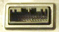
| 1 | USB GND | Ground for USB port |
| 2 | USB VBUS | Outputs power source for USB port |
| 3 | USB DATA+ | Communication signal |
| 4 | USB DATA- | Communication signal |
| 5 | USB SH | Shield for terminals No. 1, No. 2, No. 3, and No. 4 |
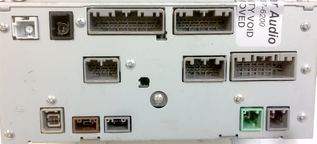
Rectangle brown and gray connectors : LVDS for center display unit gauge control module (LVDS+, LVDS-, Shield)
 correct
 incorrect