
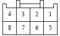
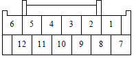
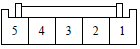
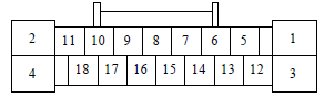
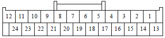
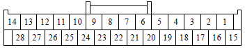
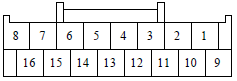
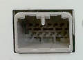
Audio Wire Harness Connectors, terminal views
| Pin Num |
Wire Color |
Signal |
|---|---|---|
| 1 | BLK | GND |
| 2 | BLU | B-CAN L |
| 3 | ORN | +B RADIO |
| 4 | PNK | B-CAN H |
| 5 | BRN | RL PRE+ (with Premium Amplifier) |
| 6 | BLU | RL PRE– (with Premium Amplifier) |
| 9 | PNK | RR PRE+ (with Premium Amplifier) |
| 10 | PUR | RR PRE– (with Premium Amplifier) |
| 11 | RED | REMOTE GND |
| 12 | WHT | SCTY2 |
| 13 | LTBLU | K-LINE |
| 15 | WHT | FL PRE+ |
| 16 | LTGRN | FL PRE– |
| 19 | GRN | FR PRE+ |
| 20 | RED | FR PRE– |
| 21 | PNK | RADIO SW (+B) |
| 22 | PNK | REMOTE |
| 23 | WHT | REMOTE SW |
| 24 | PUR | ACC |
| Pin Num |
Wire Color |
Signal |
|---|---|---|
| 1 | GRY | TELEM SIG SH |
| 2 | YEL | TELEM SIG– |
| 4 | LTBLU | RS485– |
| 5 | PUR | RS485+ |
| 6 | YEL | AUX GND |
| 7 | GRY | AUX SH GND |
| 8 | BLK | AUX SIG GND |
| 12 | BRN | TELEM SIG+ |
| 15 | GRY | SH RS485 |
| 16 | PUR | AUX DET |
| 17 | WHT | AUX R CH |
| 18 | RED | AUX L CH |
| Pin Num |
Wire Color |
Signal |
|---|---|---|
| 1 | YEL | CTR PRE+ (with Premium Amplifier) |
| 3 | BLK | CTR PRE+ (with Premium Amplifier) |
| 4 | PUR | ANC CHK2 |
| 5 | GRN | SUBW PRE+ (with Premium Amplifier) |
| 7 | LTBLU | SUBW PRE– (with Premium Amplifier) |
| Pin Num |
Wire Color |
Signal |
|---|---|---|
| 1 | YEL | GA BUS– |
| 2 | GRY | GA BUS SH |
| 3 | BLU | GA AUDIO L– |
| 4 | YEL | GA AUDIO R– |
| 5 | GRY | SH GA AUDIO |
| 6 | BLK | GA GND |
| 7 | BRN | GA BUS+ |
| 8 | LTBLU | GA SYS ON |
| 9 | PUR | GA AUDIO L+ |
| 10 | ORN | GA AUDIO R+ |
| 11 | ||
| 12 | WHT | GA +B |
| Pin Num |
Wire Color |
Signal |
|---|---|---|
| 1 | GRY | TUNE SH |
| 2 | PUR | TUNE L– |
| 3 | BLU | TUNE L+ |
| 4 | YEL | TUNE R– |
| 5 | ORN | TUNE R+ |
| Pin Num |
Wire Color |
Signal |
|---|---|---|
| 1 | BLK | GND |
| 3 | ORN | +B RADIO |
| 6 | GRY | HFT-NAVI MIC SH |
| 9 | BLK | JOG SH |
| 10 | GRN | VSP |
| 13 | GRN | HFT-NAVI MIC+ |
| 14 | RED | HFT-NAVI MIC– |
| 16 | BLU | JOG |
| 17 | WHT | F CAN-H |
| 18 | BLK | F CAN-L |
| Pin Num |
Wire Color |
Signal |
|---|---|---|
| 2 | GRY | SH CAMERA |
| 3 | RED | CAMERA V GND |
| 5 | ORN | CAMERA BIT 0 |
| 6 | YEL | BSM SW (with LaneWatch) |
| 8 | WHT | BSM CAM V GND (with LaneWatch) |
| 9 | GRY | BSM CAM SH (with LaneWatch) |
| 15 | GRN | CAMERA VIDEO |
| 16 | BLK | CAMERA VCC |
| 17 | YEL | CAMERA ADPT |
| 18 | BRN | CAMERA BIT 1 |
| 20 | BRN | BSM CAM VID (with LaneWatch) |
| 21 | BLU | BSM CAM +B (with LaneWatch) |
| 22 | GRN | BSM COMM1 (with LaneWatch) |
| 23 | YEL | BSM COMM2 (with LaneWatch) |
| 24 | BRN | BACK LT |

| Pin Num |
Wire Color |
Signal |
|---|---|---|
| 1 | USB GND | |
| 2 | USB VBUS | |
| 3 | USB DATA+ | |
| 4 | USB DATA– | |
| 5 | USB SH |
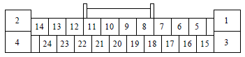
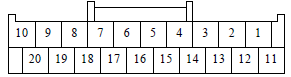
28 pin connector Rear Entertainment connector (RES)
| Pin Num |
Wire Color |
Signal |
|---|---|---|
| 1 | PNK | RR NTSC GND |
| 2 | GRY | RR NTSC SH |
| 3 | GRY | RES VID SH |
| 4 | GRY | HP R/L SH |
| 5 | WHT | HP R/L GND |
| 8 | PNK | RR AUX AUDIO GND |
| 9 | GRY | RR AUX AUDIO SH |
| 10 | ORN | RR AUX DET |
| 15 | BLU | RR NTSC |
| 16 | PNK | RES VID SIG GND |
| 17 | BLU | RES VID SIG |
| 18 | RED | HP L |
| 19 | BLK | HP R |
| 22 | BLU | RR AUX AUDIO R |
| 23 | GRN | RR AUX AUDIO L |
| Pin Num |
Wire Color |
Signal |
|---|---|---|
| 1 | GRY | RG SH |
| 2 | GRN | RG GND |
| 10 | RED | RG L+ |
Omitted pins are Not Connected.
 correct
 incorrect