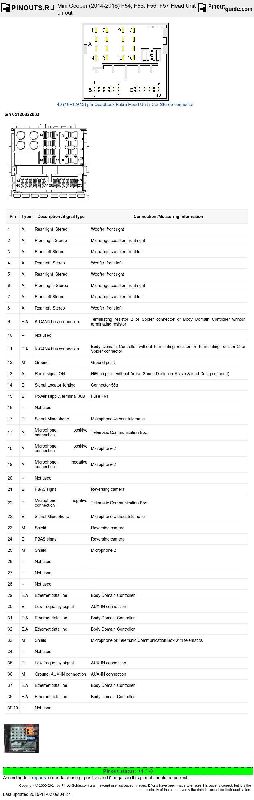
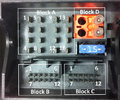
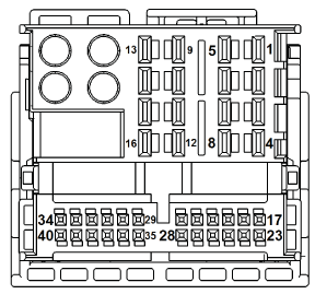
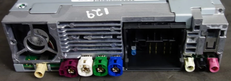
Connector View
| Pin | Type | Description /Signal type | Connection /Measuring information |
|---|---|---|---|
| 1 | A | Rear right Stereo | Woofer, front right |
| 2 | A | Front right Stereo | Mid-range speaker, front right |
| 3 | A | Front left Stereo | Mid-range speaker, front left |
| 4 | A | Rear left Stereo | Woofer, front left |
| 5 | A | Rear right Stereo | Woofer, front right |
| 6 | A | Front right Stereo | Mid-range speaker, front right |
| 7 | A | Front left Stereo | Mid-range speaker, front left |
| 8 | A | Rear left Stereo | Woofer, front left |
| 9 | E/A | K-CAN4 bus connection | Terminating resistor 2 or Solder connector or Body Domain Controller without terminating resistor |
| 10 | -- | Not used | |
| 11 | E/A | K-CAN4 bus connection | Body Domain Controller without terminating resistor or Terminating resistor 2 or Solder connector |
| 12 | M | Ground | Ground point |
| 13 | A | Radio signal ON | HiFi amplifier without Active Sound Design or Active Sound Design (if used) |
| 14 | E | Signal Locator lighting | Connector 58g |
| 15 | E | Power supply, terminal 30B | Fuse F61 |
| 16 | -- | Not used | |
| 17 | E | Signal Microphone | Microphone without telematics |
| 17 | A | Microphone, positive connection | Telematic Communication Box |
| 18 | A | Microphone, positive connection | Microphone 2 |
| 19 | A | Microphone, negative connection | Microphone 2 |
| 20 | -- | Not used | |
| 21 | E | FBAS signal | Reversing camera |
| 22 | E | Microphone, negative connection | Telematic Communication Box |
| 22 | E | Signal Microphone | Microphone without telematics |
| 23 | M | Shield | Reversing camera |
| 24 | E | FBAS signal | Reversing camera |
| 25 | M | Shield | Microphone 2 |
| 26 | -- | Not used | |
| 27 | -- | Not used | |
| 28 | -- | Not used | |
| 29 | E/A | Ethernet data line | Body Domain Controller |
| 30 | E | Low frequency signal | AUX-IN connection |
| 31 | E/A | Ethernet data line | Body Domain Controller |
| 32 | E/A | Ethernet data line | Body Domain Controller |
| 33 | M | Shield | Microphone or Telematic Communication Box with telematics |
| 34 | -- | Not used | |
| 35 | E | Low frequency signal | AUX-IN connection |
| 36 | M | Ground, AUX-IN connection | AUX-IN connection |
| 37 | E/A | Ethernet data line | Body Domain Controller |
| 38 | E/A | Ethernet data line | Body Domain Controller |
| 39,40 | -- | Not used |
Round connectors, from right to left
| Color | Functiom |
|---|---|
| pink | Connection for DAB III aerial (European version only), alternatively connection for SDARS aerial (US version only) |
| black | Connection for FM/AM aerial |
| white | Connection for FM/AM 2 aerial |
| blue | Connection 2 for USB (base plate) |
| green | Connection 3 for USB (Telematic Communication Box – TCB) |
| white | Connection 1 for USB (Telematic Communication Box – TCB) |
| brown | Connection for data line to the central information display (APIX data line) |
| beige | Connection for Bluetooth aerial |
for
2014-03/2016 Mini Cooper Hatchback Base, S, and JCW (F56)
2015-03/2016 Mini Cooper 5-Door Base and S (F55)
2015-03/2016 Mini Cooper Clubman Base, Base ALL4, S, S ALL4, and JCW ALL4 (F54)
2016-03/2016 Mini Cooper Convertible Base, S, and JCW (F57)
 correct
 incorrect