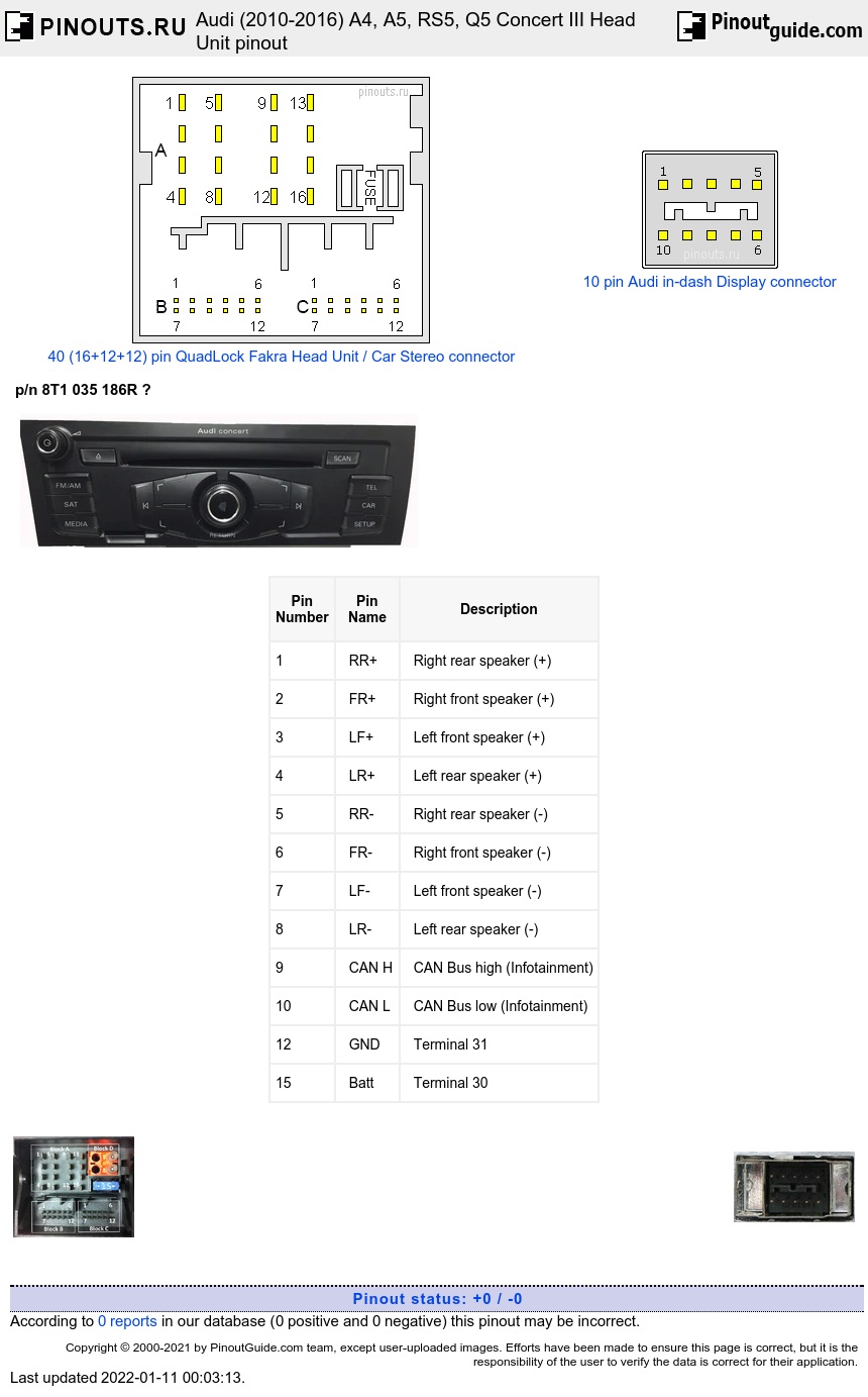

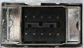
16 pin connector A (brown and black plugs)
| Pin Number |
Pin Name |
Description |
|---|---|---|
| 1 | RR+ | Right rear speaker (+) |
| 2 | FR+ | Right front speaker (+) |
| 3 | LF+ | Left front speaker (+) |
| 4 | LR+ | Left rear speaker (+) |
| 5 | RR- | Right rear speaker (-) |
| 6 | FR- | Right front speaker (-) |
| 7 | LF- | Left front speaker (-) |
| 8 | LR- | Left rear speaker (-) |
| 9 | CAN H | CAN Bus high (Infotainment) |
| 10 | CAN L | CAN Bus low (Infotainment) |
| 12 | GND | Terminal 31 |
| 15 | Batt | Terminal 30 |
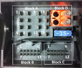
12 pin B connector (blue plug)
| Pin Number |
Pin Name |
Description |
|---|---|---|
| 1 | Left LF | Left LF-In from the External Audio Source Connection |
| 2 | LF GND | LF-In ground from the External Audio Source Connection |
| 3 | Ground | Ground |
| 4 | Batt+ | Permanent positive |
| 6 | DATA OUT | |
| 7 | Right LF | Right LF-In from the External Audio Source Connection |
| 8 | Left | Left signal |
| 9 | Right | Right signal |
| 10 | ACC+ | Positive switched |
| 11 | DATA IN | |
| 12 | CLK |
12 pin C connector (green plug)
| Pin Number |
Pin Name |
Description |
|---|---|---|
| 1 | Microphone IN (-) | |
| 2 | Right LF OUT | |
| 3 | LF OUT ground | |
| 4 | Microphone OUT (-) | |
| 5 | Left LF IN (-) | |
| 6 | LF (-) | from the cell phone preparation/ Telephone Transceiver |
| 7 | Microphone IN (+) | |
| 8 | Left LF OUT | |
| 9 | Microphone OUT (+) | |
| 10 | LF mute | wire from preliminary setup for cell phone preparation |
| 11 | Left LF IN (+) | |
| 12 | LF (+) | from the cell phone preparation/ Telephone Transceiver |
10 pin Front Information Display Connector
| Pin Number |
Function |
|---|---|
| 1 | Voltage Supply |
| 2 | Ground |
| 3 | n/c |
| 4 | Diag. Display |
| 5 | Cable Diag |
| 6 | LVDS OUT (+) |
| 7 | LVDS OUT (-) |
| 8 | LVDS OUT ground |
| 9 | Diag T0 |
| 10 | Diag T1 |
 correct
 incorrect