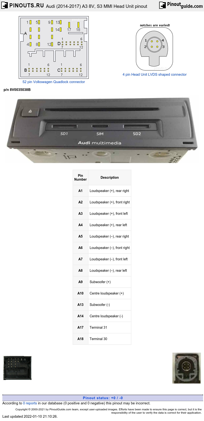
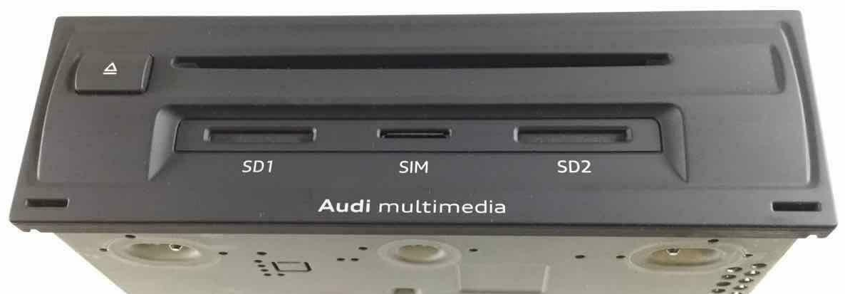
Connectors at right left are for LTE aerial, connector right to them - for SDARS (NAR vehicles) or DAB (all others). Blue connector - for GPS. White connectors are for AM/FM.
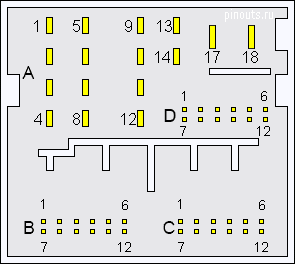
52 multi-pin connector
| Pin Number |
Description |
|---|---|
| A1 | Loudspeaker (+), rear right |
| A2 | Loudspeaker (+), front right |
| A3 | Loudspeaker (+), front left |
| A4 | Loudspeaker (+), rear left |
| A5 | Loudspeaker (–), rear right |
| A6 | Loudspeaker (–), front right |
| A7 | Loudspeaker (–), front left |
| A8 | Loudspeaker (–), rear left |
| A9 | Subwoofer (+) |
| A10 | Centre loudspeaker (+) |
| A13 | Subwoofer (-) |
| A14 | Centre loudspeaker (-) |
| A17 | Terminal 31 |
| A18 | Terminal 30 |
| Pin Number |
Description |
|---|---|
| B1 | Microphone input (+) from microphone unit in front roof module (telephone microphone ) |
| B4 | NF (+) (low frequency) from pre-fitted components for mobile phone installation |
| B5 | NF mute |
| B6 | FBAS wire (-) from reversing camera system control unit |
| B7 | Microphone input (–) from microphone unit in front roof module (telephone microphone) |
| B10 | NF (-) (low frequency) from pre-fitted components for mobile phone installation |
| B12 | FBAS wire (+) from reversing camera system control unit |
| Pin Number |
Description |
|---|---|
| C1 | NF in, earth (low frequency) |
| C2 | NF in, right-side (low frequency) |
| C3 | USB (+5 V) |
| C4 | USB (earth) |
| C7 | NF in, left-side (low frequency) |
| C8 | NF in, screen earth (low frequency) |
| Pin Number |
Description |
|---|---|
| E1 | CAN bus High to multimedia system operating unit / display unit for front information display and operating unit control unit |
| E2 | Reset to multimedia system operating unit |
| E3 | Open circuit diagnostic lead |
| E5 | Switch-on signal to telephone bracket |
| E6 | CAN bus High, infotament |
| E7 | CAN bus Low to multimedia system operating unit / display unit for front information display and operating unit control unit |
| E8 | Reset from multimedia system operating unit |
| E11 | Status signal from telephone bracket |
| E12 | CAN bus Low, infotament |
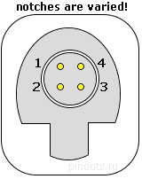
4 pin light-brown connector (for external audio source)
| Pin Number |
Description |
|---|---|
| 1 | D (+) |
| 2 | iPod detected |
| 3 | D (–) |
| 4 | Earth |
4 pin turquoise connector (for display unit)
| Pin Number |
Description |
|---|---|
| 1 | LVDS (–) |
| 2 | LIN |
| 3 | LVDS (+) |
| 4 | Earth |
Yellow plug on the right is the MOST150 optical interface, which can be used to connect an external device like DVD player, amplifier, etc.


 correct
 incorrect