
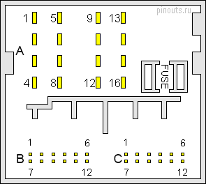
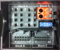
16 pin A connector
| Pin Number |
Function |
|---|---|
| 1 | Wake UP to Multimedia System Control Head |
| 4 | Res HU to multimedia system control head |
| 5 | Res BT to multimedia system control head |
| 6 | Ground (GND) to multimedia system control head |
| 11 | NF mute from preliminary setup for cell phone preparation |
| 12 | Terminal 31 |
| 13 | Voltage supply for the front information display control head |
| 14 | Ring-break diagnostic cable |
| 15 | Terminal 30 |
| 16 | Voltage supply to Multimedia System Control Head |
12 pin B connector
| Pin Number |
Function |
|---|---|
| 1 | Data to the multimedia system control head |
| 3 | Data (+) to Front Information Display Control Head |
| 4 | Data (-) to Front Information Display Control Head |
| 5 | Data from multimedia system control head |
12 pin C connector
| Pin Number |
Function |
|---|---|
| 5 | Data (-) from Front Information Display Control Head |
| 7 | Ground (GND) to Multimedia Control Head |
| 11 | Data (+) from Front Information Display Control Head |
Following pins are also still connected with the internet access control module (from MY 13). 3 - USB (+5 V) 4 - USB (ground) 6 - Detect.
 correct
 incorrect