
| Pin Number |
Pin Name |
Description |
|---|---|---|
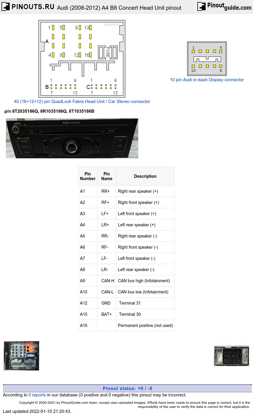
| A1 | RR+ | Right rear speaker (+) |
| A2 | RF+ | Right front speaker (+) |
| A3 | LF+ | Left front speaker (+) |
| A4 | LR+ | Left rear speaker (+) |
| A5 | RR- | Right rear speaker (-) |
| A6 | RF- | Right front speaker (-) |
| A7 | LF- | Left front speaker (-) |
| A8 | LR- | Left rear speaker (-) |
| A9 | CAN-H | CAN bus high (Infotainment) |
| A10 | CAN-L | CAN bus low (Infotainment) |
| A12 | GND | Terminal 31 |
| A15 | BAT+ | Terminal 30 |
| A16 | Permanent positive (not used) |
12 pin B connector
| Pin Number |
Pin Name |
Description |
|---|---|---|
| B1 | Left LF IN+ | Left IN for the external audio source connection |
| B2 | LF GND | LF for the external audio source connection ground |
| B7 | Right LF IN | Right IN for the external audio source connection |
12 pin C connector
| Pin Number |
Pin Name |
Description |
|---|---|---|
| C2 | Right LF OUT | |
| C3 | LF OUT ground | |
| C4 | Microphone OUT (-) | |
| C5 | Left LF IN (-) | |
| C6 | LF (-) | from Telephone Transceiver |
| C7 | Microphone IN (+) | |
| C8 | Left LF OUT | |
| C9 | Microphone OUT (+) | |
| C10 | LF mute | |
| C11 | Left LF IN (+) | |
| C12 | LF (+) | for the telephone transceiver |
10 pin Front Information Display Connector
| Pin Number |
Function |
|---|---|
| 1 | Voltage Supply |
| 2 | Ground |
| 3 | n/c |
| 4 | Diag. Display |
| 5 | Cable Diag |
| 6 | LVDS OUT (+) |
| 7 | LVDS OUT (-) |
| 8 | LVDS OUT ground |
| 9 | Diag T0 |
| 10 | Diag T1 |
 correct
 incorrect