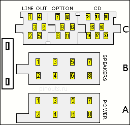
| Pin Number | Wire Colour | Connection |
| A1 | No Connection | |
| A2 | No Connection | |
| A3 | No Connection | |
| A4 | Blue | 12v Switched |
| A5 | Remote Out | |
| A6 | Brown/White or Green/Blue | Lighting Input |
| A7 | Pink/White or Pink | 12v Permanent |
| A8 | Brown | Earth |
| B1 | Yellow | Tweeter Right + |
| B2 | Yellow/Black | Tweeter Right - |
| B3 | Green/Yellow | Speaker Right + |
| B4 | Grey/Green | Speaker Right - |
| B5 | Green/Blue | Speaker Left + |
| B6 | Grey/Brown | Speaker Left - |
| B7 | Green | Tweeter Left + |
| B8 | Green/Black | Tweeter Left - |
| C1 | No Connection | |
| C2 | No Connection | |
| C3 | No Connection | |
| C4 | No Connection | |
| C5 | No Connection | |
| C6 | 12v Permanent | |
| C7 | 12v Switched | |
| C8 | Radio Mute | |
| C9 | Earth | |
| C10 | 12v Lighting | |
| C11 | Phone Speaker + | |
| C12 | Phone Speaker - | |
| C13 | CD Changer Signal | |
| C14 | No Connection | |
| C15 | Earth | |
| C16 | 12v Permanent | |
| C17 | 12v Switched | |
| C18 | CD Changer Input - | |
| C19 | CD Changer Input Left | |
| C20 | CD Changer Input Right |
If you did publish instruction for Do-It-Yourself device with this pinout, share the link with us.


 correct
 incorrect