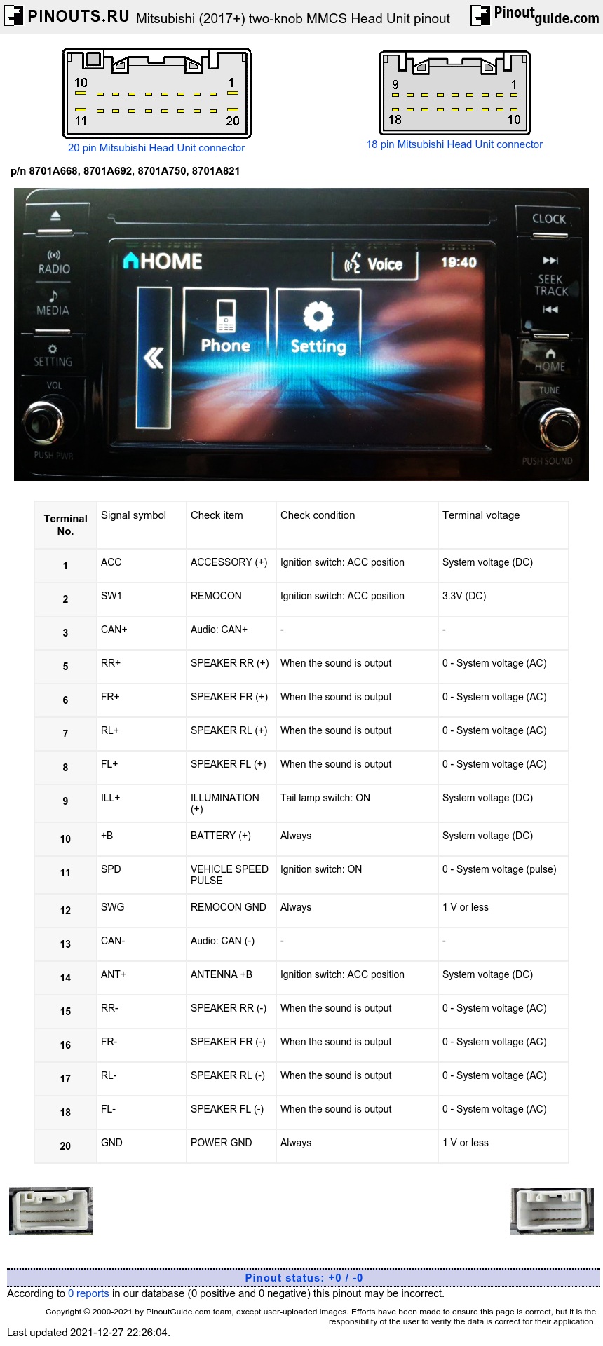
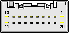
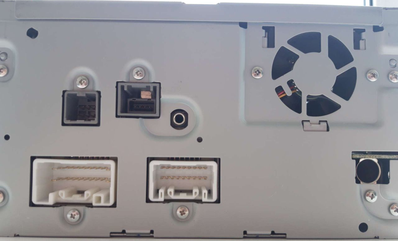
20-pin connector (white receptacle)
| Terminal No. | Signal symbol | Check item | Check condition | Terminal voltage |
|---|---|---|---|---|
| 1 | ACC | ACCESSORY (+) | Ignition switch: ACC position | System voltage (DC) |
| 2 | SW1 | REMOCON | Ignition switch: ACC position | 3.3V (DC) |
| 3 | CAN+ | Audio: CAN+ | - | - |
| 5 | RR+ | SPEAKER RR (+) | When the sound is output | 0 - System voltage (AC) |
| 6 | FR+ | SPEAKER FR (+) | When the sound is output | 0 - System voltage (AC) |
| 7 | RL+ | SPEAKER RL (+) | When the sound is output | 0 - System voltage (AC) |
| 8 | FL+ | SPEAKER FL (+) | When the sound is output | 0 - System voltage (AC) |
| 9 | ILL+ | ILLUMINATION (+) | Tail lamp switch: ON | System voltage (DC) |
| 10 | +B | BATTERY (+) | Always | System voltage (DC) |
| 20 | SPD | VEHICLE SPEED PULSE | Ignition switch: ON | 0 - System voltage (pulse) |
| 18 | SWG | REMOCON GND | Always | 1 V or less |
| 17 | CAN- | Audio: CAN (-) | - | - |
| 16 | ANT+ | ANTENNA +B | Ignition switch: ACC position | System voltage (DC) |
| 15 | RR- | SPEAKER RR (-) | When the sound is output | 0 - System voltage (AC) |
| 14 | FR- | SPEAKER FR (-) | When the sound is output | 0 - System voltage (AC) |
| 13 | RL- | SPEAKER RL (-) | When the sound is output | 0 - System voltage (AC) |
| 12 | FL- | SPEAKER FL (-) | When the sound is output | 0 - System voltage (AC) |
| 11 | GND | POWER GND | Always | 1 V or less |
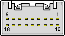
18-pin connector (white receptacle)
| Terminal No. | Signal symbol | Check item | Check condition | Terminal voltage |
|---|---|---|---|---|
| 3 | AAR+ | HFM/USB S-INPUT RIGHT | When the hands free-ECU operation | 1.2 Vrms (AC) |
| 4 | AAL+ | HFM/USB S-INPUT LEFT | When the hands free-ECU operation | 1.2 Vrms (AC) |
| 6 | TIR+ | IE-BUS INPUT RIGHT (+) | - | - |
| 7 | TIL+ | IE-BUS INPUT LEFT (+) | - | - |
| 8 | AMPO | IE-BUS POWER ON | Ignition switch: ACC position | 1 V or less |
| 9 | D-S+ | IE-BUS (+) | Ignition switch: ACC position | More than 120 mV |
| 12 | AA- | HFM/USB INPUT GND | When the hands free-ECU operation | 1.2 Vrms (AC) |
| 15 | TIR- | IE-BUS INPUT RIGHT (-) | - | - |
| 16 | TIL- | IE-BUS INPUT LEFT (-) | - | - |
| 18 | D-S- | IE-BUS (-) | Ignition switch: ACC position | More than 120 mV |
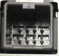
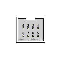
8-pin connector (gray receptacle, Vehicles with display audio)
| Terminal No. | Signal symbol | Check item | Check condition | Terminal voltage |
| 1 | +6.5V | May be not connected | 6.5V | |
| 4 | BATTERY (+) | Always | System voltage (DC) | |
| 5 | GND | May be not connected | 0V | |
| 6 | CMP+ | CAMERA SIGNAL |
|
1 Vp-p (AC) |
| 7 | CMP- | SHIELD (CAMERA) | Always | 1 V or less |
| 8 | GND | Always | 1 V or less |


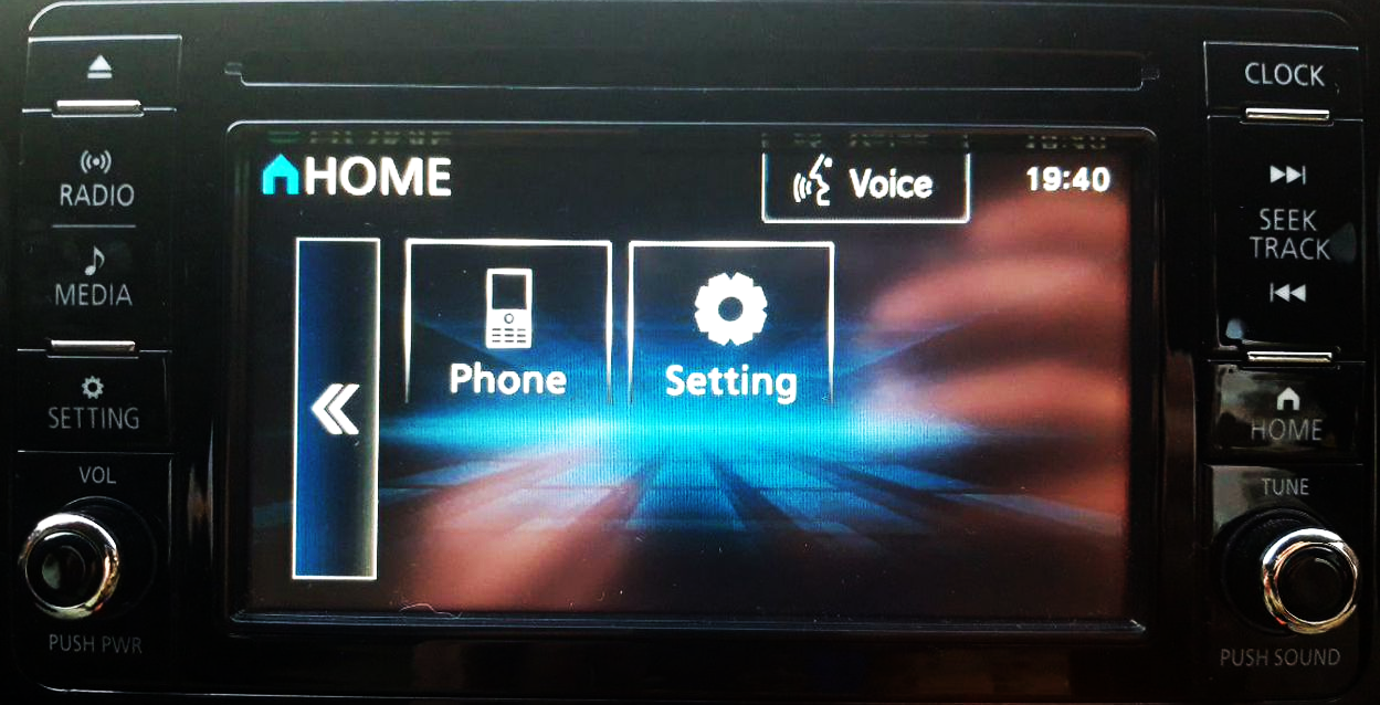

 correct
 incorrect