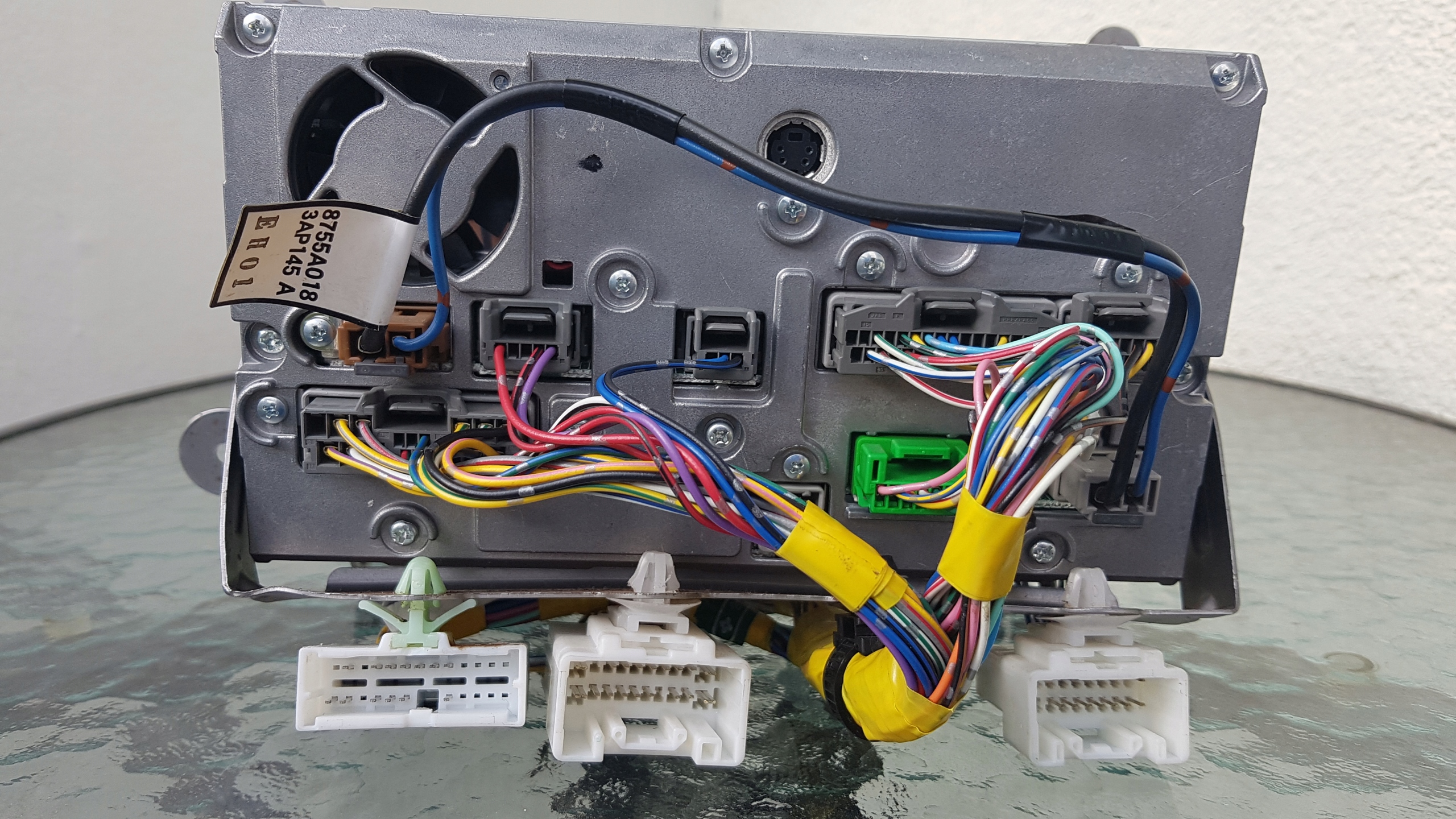
Should be also compatible with the following models (not tested!):
NR-261EM (for Europa)
- MMCS C-01 8750A139 (NR-261EM-07CTR0);
- MMCS C-02 8750A245 (NR-261EM-11CTR1);
- MMCS E-01 8750A070 (NR-261EM-07AIR0);
- MMCS E-02 8750A143 (NR-261EM-07AIR1);
- MMCS E-03 8750A184 (NR-261EM-07AIR2);
- MMCS E-04 8750A210 (NR-261EM-07AIR3);
- MMCS E-05 8750A239 (NR-261EM-07AIR4);
- MMCS E-06 8750A327 (NR-261EM-07AIR5);
- MMCS P-01 8750A138 (NR-261EM-07PUG0);
- MMCS P-02 8750A242 (NR-261EM-11PUG1)
NR-261JM (for Japan)
- MMCS J-02 8750A072 (NR-261JM-07PAJ0);
- MMCS J-03 8750A141 (NR-261JM-07PAJ1);
- MMCS J-04 8750A115 (NR-261JM-07PAJ2);
- MMCS J-05 8750A224 (NR-261JM-07PAJ3);
- MMCS J-06 8750A326
NR-261UM (for USA)
- MMCS N-01 8750A069 (NR-261UM-07LAN0);
- MMCS N-02 8750A142;
- MMCS N-03 8750A183(NR-261UM-07LAN1);
- MMCS N-04 8750A209;
- MMCS N-05 8750A238
NR-261RM (for Russia)
- MMCS R-01 8750A169;
- MMCS R-02 8750A170;
- MMCS R-03 8750A211 (NR-261RM-07PAJ2)
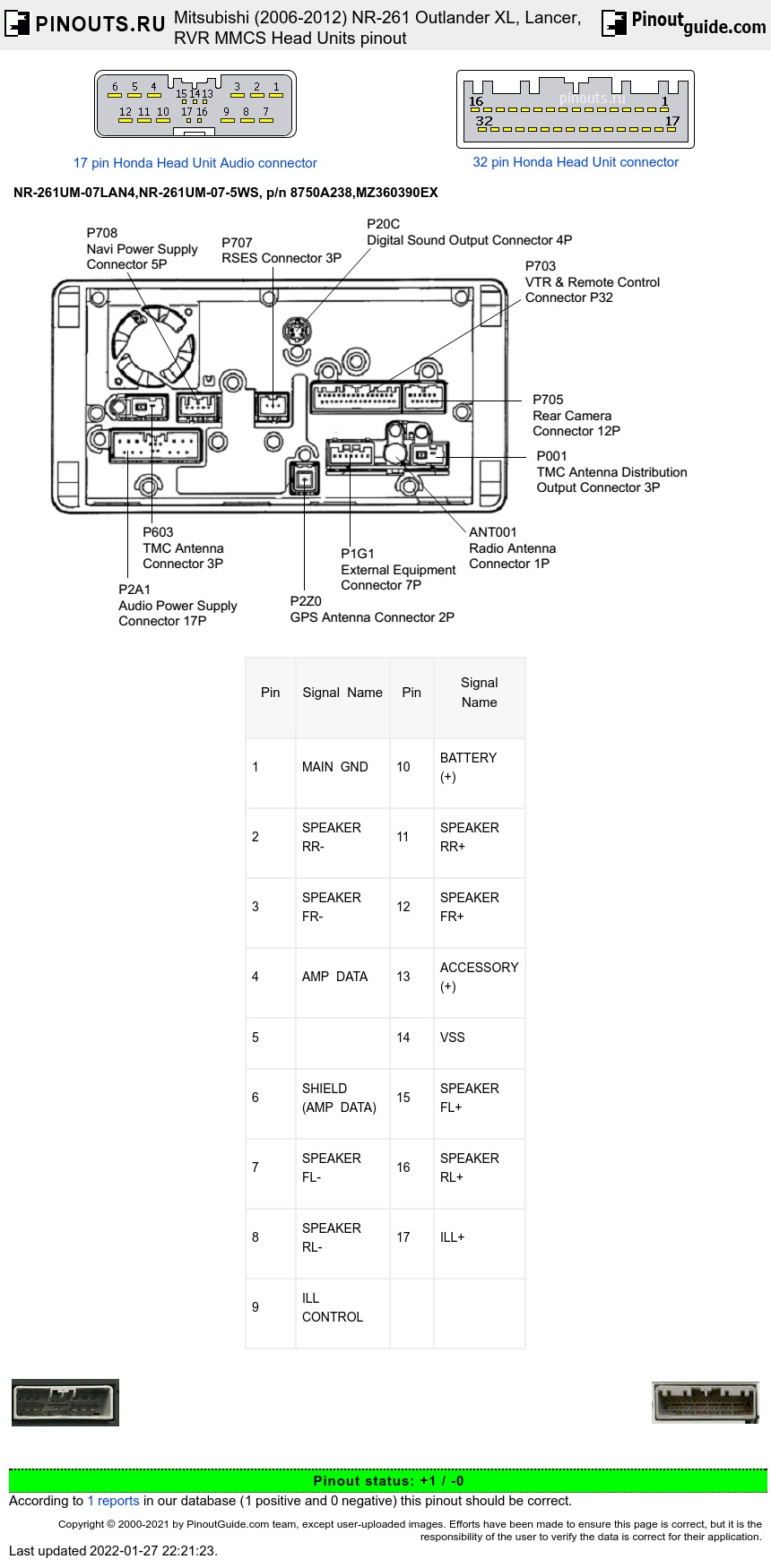
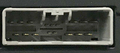
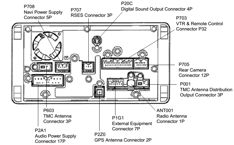
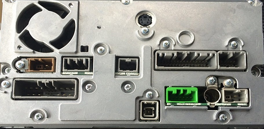
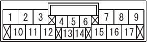
17 pin Audio Power Supply Connector
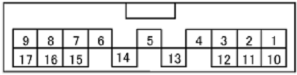
|
Pin |
Signal Name |
Pin |
Signal Name |
|---|---|---|---|
|
1 |
MAIN GND |
10 |
BATTERY (+) |
|
2 |
SPEAKER RR- |
11 |
SPEAKER RR+ |
|
3 |
SPEAKER FR- |
12 |
SPEAKER FR+ |
|
4 |
AMP DATA |
13 |
ACCESSORY (+) |
|
5 |
|
14 |
VSS |
|
6 |
SHIELD (AMP DATA) |
15 |
SPEAKER FL+ |
|
7 |
SPEAKER FL- |
16 |
SPEAKER RL+ |
|
8 |
SPEAKER RL- |
17 |
ILL+ |
|
9 |
ILL CONTROL |
|
|
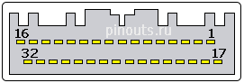
32 pin VTR & Remote Control Connector
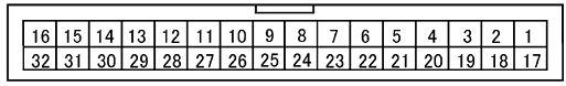
|
Pin |
Signal Name |
Pin |
Signal Name |
|---|---|---|---|
|
1 |
- |
17 |
- |
|
2 |
- |
18 |
- |
|
3 |
TEL MUTE |
19 |
- |
|
4 |
STEERING REMOTE |
20 |
SHIELD (STEERING REMOTE) |
|
5 |
- |
21 |
SHIELD (CAN-BOX DATA) |
|
6 |
- |
22 |
- |
|
7 |
- |
23 |
- |
|
8 |
SHIELD (VIDEO-2L/R) |
24 |
VIDEO2 DETECT |
|
9 |
VIDEO2-R |
25 |
VIDEO2-L |
|
10 |
VIDEO2-IN |
26 |
SHIELD (VIDEO2-IN) |
|
11 |
HEM SIGNAL (-)-GND |
27 |
- |
|
12 |
HFM SIGNAL (+)-R |
28 |
HEM SIGNAL(+)-L |
|
13 |
- |
29 |
- |
|
14 |
CAN-BOX DATA RX |
30 |
CAN-BOX DATA TX |
|
15 |
- |
31 |
CAN-BOX DATA CLK |
|
16 |
- |
32 |
- |
12 pin Rear Camera Connector
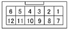
|
Pin |
Signal Name |
|---|---|
|
1 |
CAMERA DETECT |
|
2 |
SHIELD (CAMERA) |
|
4 |
CAMERA SIGNAL |
|
5 |
GND (RC) |
|
6 |
VCC (RC6.5V) |
7 pin External Equipment Connector

|
Pin |
Signal Name |
|---|---|
|
1 |
SIRIUS-R |
|
2 |
S-GND (SIRIUS-L/R) |
|
3 |
SIRIUS-L |
|
4 |
BUS(-) |
|
5 |
BUS(+) |
|
6 |
AMP POWER ON |
|
7 |
ANTENNA-POWER |
5 pin Navi Power Supply Connector
|
Pin |
Signal Name |
|---|---|
|
1 |
GND |
|
2 |
PS-R |
|
5 |
BATTERY (+) |
3 pin Rear Seat Entertainment

|
Pin |
Signal Name |
|---|---|
|
1 |
Shield (Rear) |
|
2 |
Rear Signal |
4 pin jack/plug Version Up Key Terminal
|
Pin |
Signal Name |
|---|---|
|
1 |
I2C-SDA |
|
2 |
GND |
|
3 |
I2C-SCL |
|
4 |
I2C-VCC |
The same pinout with alternative numbering and some details
17 pin Audio Connector
| Terminal No. | Signal symbol | Check condition | Terminal voltage |
| 2 | SPEAKER RL (-) | When the sound is output | 0 - System voltage (AC) |
| 3 | SPEAKER FL (-) | When the sound is output | 0 - System voltage (AC) |
| 6 | AMP DATA | Ignition switch: ON | 0 - System voltage (DC) |
| 7 | SPEAKER FR (-) | When the sound is output | 0 - System voltage (AC) |
| 8 | SPEAKER RR (-) | When the sound is output | 0 - System voltage (AC) |
| 9 | MAIN GND | Always | 1 V or less |
| 10 | ILLUMINATION (+) | Tail lamp switch: ON | System voltage (DC) |
| 11 | SPEAKER RL (+) | When the sound is output | 0 - System voltage (AC) |
| 12 | SPEAKER FL (+) | When the sound is output | 0 - System voltage (AC) |
| 13 | VSS | Ignition switch: ON | 0 - System voltage (pulse) |
| 14 | ACCESSORY (+) | Ignition switch: ACC position | System voltage (DC) |
| 15 | SPEAKER FR (+) | When the sound is output | 0 - System voltage (AC) |
| 16 | SPEAKER RR (+) | When the sound is output | 0 - System voltage (AC) |
| 17 | BATTERY (+) | Always | System voltage (DC) |
5 pin Connector
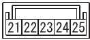
| Terminal No. | Signal symbol | Check condition | Terminal voltage |
| 21 | BATTERY (+) | Always | System voltage (DC) |
| 24 | PS-R | Sift lever or selector lever : R position Ignition switch: ON position |
Hi : 5Mid : OpenLo : 0 |
| 25 | GND | Always | 1 V or less |
3 pin Rear Camera Connector

| Terminal No. | Signal symbol | Check condition | Terminal voltage |
| 32 | REAR SIGNAL | When the image is output | 1 Vp-p (AC) |
| 33 | SHIELD | Always | 1 V or less |
7 pin Green Connector
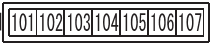
| Terminal No. | Signal symbol | Check condition | Terminal voltage |
| 101 | ANTENNA POWER ON | Ignition switch: ACC position | System voltage (DC) |
| 102 | AMP POWER ON | Ignition switch: ACC position | 1 V or less |
| 103 | IE-BUS (+) | Ignition switch: ACC position | More than 120mV |
| 104 | IE-BUS (-) | Ignition switch: ACC position | More than 120mV |
32 pin Handsfree Misc Connector
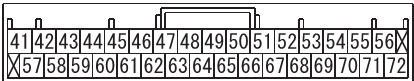
| Terminal No. | Signal symbol | Check condition | Terminal voltage |
| 43 | CAN-BOX DATA RX | Ignition switch: ACC position | 2 - System voltage(DC) |
| 45 | HFM SIGNAL (+) | When the hands free system operation | 1.2 Vrms (AC) |
| 46 | HFM SIGNAL (-) | When the hands free system operation | 1.2 Vrms (AC) |
| 47 | VIDEO2-IN | When the image is input | 1Vp-p (AC) |
| 48 | VIDEO2-R | When the sound is input | 1.2Vrms (AC) |
| 49 | SEIELD (VIDEO2-L/R) | Always | 1 V or less |
| 53 | AUDIO REMOTE | Ignition switch: ACC position | 3.3V (DC) |
| 58 | CAN-BOX DATA CLK | Ignition switch: ACC position | 1 - 5V (DC) |
| 59 | CAN-BOX DATA TX | Ignition switch: ACC position | 5V (DC) |
| 61 | HFM SIGNAL (+)-L | When the hands free ECU or USB box operation | 1.2 Vrms (AC) |
| 63 | SEIELD (VIDEO2-IN) | Always | Approximately 0 V |
| 64 | VIDEO2-L | When the sound is input | 1.2Vrms (AC) |
| 65 | VIDEO2 DETECT | Always | 1 V or less |
| 69 | SEIELD (STEERING REMO) | Always | 1 V or less |
12 pin Camera Connector
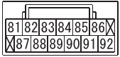
| Terminal No. | Signal symbol | Check condition | Terminal voltage |
| 81 | VCC (RC 6.5v) | Sift lever or selector lever : R position Ignition switch: ON position |
5.8 - 7.0V (DC) |
| 82 | GND | Always | - |
| 83 | CAMERA SIGNAL | Sift lever or selector lever : R position Ignition switch: ON position |
1Vp-p (AC) |
| 85 | SHIELD (CAMERA) | Always | - |
| 86 | CAMERA DETECT | Sift lever or selector lever : R position Ignition switch: ON position |
0 - 5V (DC) |
 correct
 incorrect