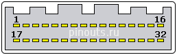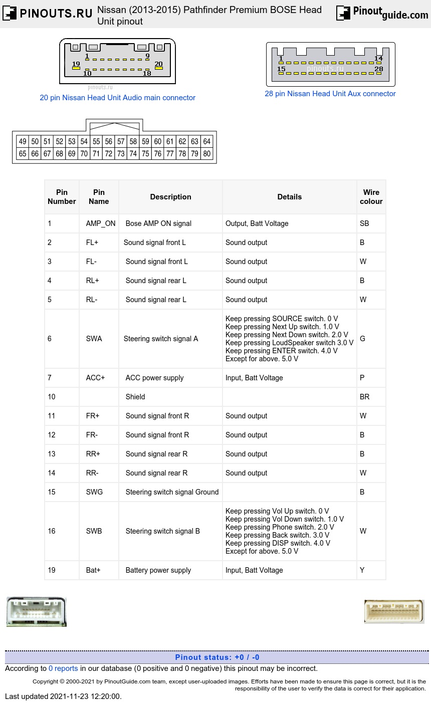

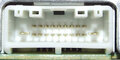
20 pin Main Audio Connector
| Pin Number |
Pin Name |
Description | Details | Wire colour |
|---|---|---|---|---|
| 1 | AMP_ON | Bose AMP ON signal | Output, Batt Voltage | SB |
| 2 | FL+ | Sound signal front L | Sound output | B |
| 3 | FL- | Sound signal front L | Sound output | W |
| 4 | RL+ | Sound signal rear L | Sound output | B |
| 5 | RL- | Sound signal rear L | Sound output | W |
| 6 | SWA | Steering switch signal A | Keep pressing SOURCE switch. 0 V Keep pressing Next Up switch. 1.0 V Keep pressing Next Down switch. 2.0 V Keep pressing LoudSpeaker switch 3.0 V Keep pressing ENTER switch. 4.0 V Except for above. 5.0 V |
G |
| 7 | ACC+ | ACC power supply | Input, Batt Voltage | P |
| 10 | Shield | BR | ||
| 11 | FR+ | Sound signal front R | Sound output | W |
| 12 | FR- | Sound signal front R | Sound output | B |
| 13 | RR+ | Sound signal rear R | Sound output | B |
| 14 | RR- | Sound signal rear R | Sound output | W |
| 15 | SWG | Steering switch signal Ground | B | |
| 16 | SWB | Steering switch signal B | Keep pressing Vol Up switch. 0 V Keep pressing Vol Down switch. 1.0 V Keep pressing Phone switch. 2.0 V Keep pressing Back switch. 3.0 V Keep pressing DISP switch. 4.0 V Except for above. 5.0 V |
W |
| 19 | Bat+ | Battery power supply | Input, Batt Voltage | Y |
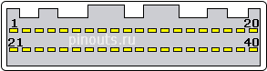
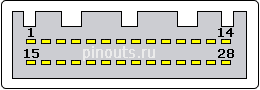
28 pin AUX connector
| Pin Number |
Pin Name |
Description | Details | Wire colour |
|---|---|---|---|---|
| 24 | AUX_L+ | AUX sound signal L | Input, When front AUX mode is selected. |
R |
| 26 | Sound Signal L | Output. When DVD or USB mode is selected on headrest display unit |
W | |
| 27 | Sound Signal R | Output. When DVD or USB mode is selected on headrest display unit |
B | |
| 37 | Shield | |||
| 38 | AUX_R+ | AUX sound signal R | Input, When front AUX mode is selected. |
W |
| 39 | AUX_GND | AUX sound signal Ground | B | |
| 40 | Sound Signal L Ground | R | ||
| 41 | Sound Signal R Ground | G | ||
| 42 | Shield |
32 pin Misc connector

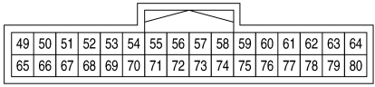
| Pin Number |
Description | Details | Wire colour |
|---|---|---|---|
| 53 | Parking brake signal | Input, 0V Parking brake is applied. 12V Parking brake is released. |
G |
| 55 | Composite image signalground | W | |
| 56 | Composite image signal | Output, at DVD image is displayed | W |
| 57 | I-Key Memory | BG | |
| 60 | Microphone VCC | +5V Output | W |
| 61 | Communication signal(CONT→DISP) | Output when adjusting display brightness. |
W |
| 62 | CAN-L | Input/Output | P |
| 63 | AV communication signal (L) | Input/Output | LG |
| 64 | M CAN–L TRM | LG | |
| 67 | MR output | P | |
| 68 | Ignition signal | +12v when ignition switch ON | LG |
| 69 | Reverse signal | +12V when selector lever is in R position, 0V otherwise | R |
| 70 | Vehicle speed signal (8-pulse) | Input , when vehicle speed is approx. 40 km/h | GR |
| 71 | Shield | ||
| 72 | Composite image synchro-nizing signal | Output, at DVD image is displayed | R |
| 75 | Microphone signal | Input | B |
| 76 | Shield | B | |
| 77 | Communication signal(DISP→CONT) | Output when adjusting display brightness. |
|
| 78 | CAN-H | Input/Output | L |
| 79 | AV communication signal (H) | Input/Output | SB |
| 80 | M CAN–H TRM | SB |
40 pin connector


| Pin Number |
Description | Details | Wire colour |
|---|---|---|---|
| 83 | Camera power supply | +6V Output when selector lever in “R” position | R |
| 84 | Camera Ground | W | |
| 91 | AUX image signal | Input when front AUX image is displayed | W |
| 92 | AUX image signal ground | B | |
| 94 | Shield | ||
| 97 | Disk eject signal | 0V when pressing eject button. +5V otherwise. | Y |
| 98 | Switch Ground | V | |
| 105 | Composite image signal ground | W | |
| 106 | Shield | ||
| 107 | Composite image signal | Output when DVD, USB or front AUX image is displayed on headrest display unit | B |
5 pin USB Connector
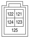
| Pin Number |
Description | Details | Wire colour |
|---|---|---|---|
| 121 | V BUS signal | W | |
| 122 | USB Ground | G | |
| 123 | USB D+ | L | |
| 124 | USB D- | R | |
| 125 | Shield |
3 pin Antenna Connector
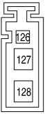
| Pin Number |
Description | Details | Wire colour |
|---|---|---|---|
| 126 | Antenna amp. ON signal | B | |
| 127 | AM-FM main | B | |
| 128 | FM sub | B |
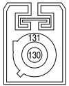
| Pin Number |
Description | Details | Wire colour |
|---|---|---|---|
| 130 | GPS antenna signal, +5V | B | |
| 131 | GPS antenna signal Ground | B |
P/N 25915-3KF0A, 25915-3KF0B, 25915-3KF0C, 25915-3KF0D, 25915-3KF0E, 25915-3LZ0A, 25915-3LZ0B, 25915-3LZ0C, 25915-3LZ0E, 25915-3LZ1A, 25915-3LZ1B, 25915-3WY2C

 correct
 incorrect