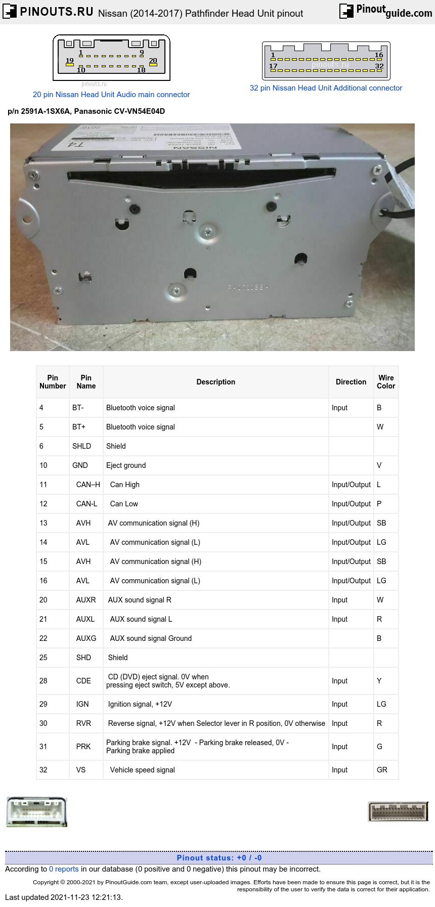


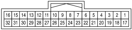
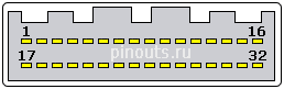
| Pin Number |
Pin Name |
Description | Direction | Wire Color |
|---|---|---|---|---|
| 4 | BT- | Bluetooth voice signal | Input | B |
| 5 | BT+ | Bluetooth voice signal | W | |
| 6 | SHLD | Shield | ||
| 10 | GND | Eject ground | V | |
| 11 | CAN–H | Can High | Input/Output | L |
| 12 | CAN-L | Can Low | Input/Output | P |
| 13 | AVH | AV communication signal (H) | Input/Output | SB |
| 14 | AVL | AV communication signal (L) | Input/Output | LG |
| 15 | AVH | AV communication signal (H) | Input/Output | SB |
| 16 | AVL | AV communication signal (L) | Input/Output | LG |
| 20 | AUXR | AUX sound signal R | Input | W |
| 21 | AUXL | AUX sound signal L | Input | R |
| 22 | AUXG | AUX sound signal Ground | B | |
| 25 | SHD | Shield | ||
| 28 | CDE | CD (DVD) eject signal. 0V when pressing eject switch, 5V except above. |
Input | Y |
| 29 | IGN | Ignition signal, +12V | Input | LG |
| 30 | RVR | Reverse signal, +12V when Selector lever in R position, 0V otherwise | Input | R |
| 31 | PRK | Parking brake signal. +12V - Parking brake released, 0V - Parking brake applied |
Input | G |
| 32 | VS | Vehicle speed signal | Input | GR |
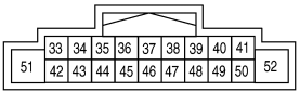
| Pin Number |
Pin Name |
Description | Direction | Wire Color |
|---|---|---|---|---|
| 34 | FL+ | front door speaker and instrument panel tweeter | Audio Output | SB |
| 35 | FL- | front door speaker and instrument panel tweeter | Audio Output | V |
| 36 | RL+ | rear door speaker | Audio Output | BR |
| 37 | RL- | rear door speaker | Audio Output | Y |
| 38 | SWA+ | Steering switch signal A Press SOURCE switch 0V Press Next Up switch 1.0V Press Next Down switch 2.0V Press Phone Loudspeaker switch 3.0V Press ENTER switch 4.0V Except above 5.0V |
Input | G |
| 39 | Acc | ACC power supply +12V | Input | P |
| 41 | Ill+ | Illumination signal, 0V - Lighting switch OFF, +12V - Lighting switch ON |
Input | R |
| 43 | FR+ | front door speaker and instrument panel tweeter | Audio Output | BR |
| 44 | FR- | front door speaker and instrument panel tweeter | Audio Output | Y |
| 45 | RR+ | rear door speaker | Audio Output | L |
| 46 | RR- | rear door speaker | Audio Output | SB |
| 47 | SWG | Steering switch signal Ground | B | |
| 48 | SWB | Steering switch signal B Press Vol Down switch 0V Press Vol Up switch 1.0V Press Phone switch 2.0V Press Back switch 3.0V Press DISP switch 4.0V Except above 5.0V |
Input | W |
| 51 | Bat+ | Battery power supply | Input | Y |
| 52 | GND | Ground | B |
| Pin Number |
Description | Direction | Wire Color |
|---|---|---|---|
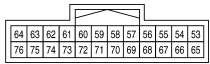
| 53 | Composite image signal. When camera image or AUX image displayed |
Output | B |
| 54 | Composite image signal ground | Output | W |
| 55 | RGB signal (B: blue) | Output | W |
| 56 | RGB signal (G: green) | Output | B |
| 57 | RGB signal (R: red) | Output | R |
| 58 | RGB synchronizing signal | Output | B |
| 59 | Shield (RGB SYN GND) | ||
| 60 | RGB area (YS) signal | Output | W |
| 61 | Communication signal(DISP→CONT) (Adjusting display brightness) | Input |
B |
| 62 | Horizontal synchronizing(HP) signal | Input | G |
| 63 | Signal ground | B | |
| 64 | Signal VCC +9V | ||
| 66,67,72 | Shield | ||
| 73 | Communication signal(CONT→DISP (Adjusting display brightness) | Output | W |
| 74 | Vertical synchronizing (VP) signal | Input | R |
| 75 | Inverter ground | LG | |
| 76 | Inverter VCC (+9V) | L |
| Pin Number |
Description | Direction | Wire Color |
|---|---|---|---|
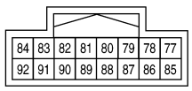
| 82 | Camera image signal | Input | B |
| 83 | AUX image signal | Input | W |
| 87 | Camera power supply (+6V when Selector lever in “R” position) | R | |
| 88 | Camera ground | W | |
| 89,90 | Shield | ||
| 91 | AUX image signal ground | B |


| Pin Number |
Description | Direction | Wire Color |
|---|---|---|---|
| 93 | Satellite radio sound signal L- |
Input when Satellite radio mode selected | W |
| 94 | Satellite radio sound signal L+ |
Input when Satellite radio mode selected | B |
| 95 | Satellite radio sound signal R- |
Input when Satellite radio mode selected | R |
| 96 | Satellite radio sound signal R+ |
Input when Satellite radio mode selected | G |
| 97,98 | Shield | ||
| 100 | Request signal(SAT→CONT) | Input | W |
| 101 | Communication signal(SAT→CONT | Input | B |
| 102 | Communication signal(CONT→SAT | Output | R |
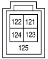
| Pin Number |
Description | Direction | Wire Color |
|---|---|---|---|
| 121 | V BUS | W | |
| 122 | USB Ground | G | |
| 123 | USB D+ | L | |
| 124 | USB D- | R | |
| 125 | Shield |
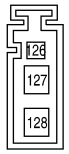
| Pin Number |
Description | Direction | Wire Color |
|---|---|---|---|
| 126 | Antenna amp. ON signal | B | |
| 127 | B | ||
| 128 | B |
 correct
 incorrect