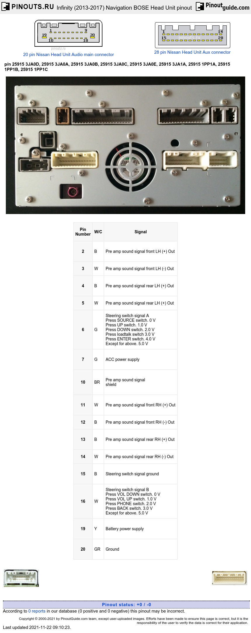

| Pin Number |
W/C | Signal |
|---|---|---|
| 2 | B | Pre amp sound signal front LH (+) Out |
| 3 | W | Pre amp sound signal front LH (-) Out |
| 4 | B | Pre amp sound signal rear LH (+) Out |
| 5 | W | Pre amp sound signal rear LH (+) Out |
| 6 | G | Steering switch signal A Press SOURCE switch. 0 V Press UP switch. 1.0 V Press DOWN switch. 2.0 V Press loadtalk switch 3.0 V Press ENTER switch. 4.0 V Except for above. 5.0 V |
| 7 | G | ACC power supply |
| 10 | BR | Pre amp sound signal shield |
| 11 | W | Pre amp sound signal front RH (+) Out |
| 12 | B | Pre amp sound signal front RH (-) Out |
| 13 | B | Pre amp sound signal rear RH (+) Out |
| 14 | W | Pre amp sound signal rear RH (-) Out |
| 15 | B | Steering switch signal ground |
| 16 | W | Steering switch signal B Press VOL DOWN switch. 0 V Press VOL UP switch. 1.0 V Press PHONE switch. 2.0 V Press BACK switch. 3.0 V Except for above. 5.0 V |
| 19 | Y | Battery power supply |
| 20 | GR | Ground |
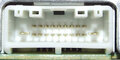
W/C stands for Wire Color. It is for Infinity QX60 2014 and very dependent on model and model year.
| Pin Number |
W/C | Signal |
|---|---|---|
| 24 | W | Auxiliary sound signal LH (+) In |
| 26 | W | Headphone sound signal LH (+) Out |
| 27 | B | Headphone sound signal RH (+) Out |
| 37 | shield | |
| 38 | R | Auxiliary sound signal RH (+) In |
| 39 | B | Auxiliary sound signal LH (-), RH (-) In |
| 40 | R | Headphone sound signal LH (-) Out |
| 41 | G | Headphone sound signal RH (-) Out |
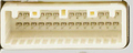
W/C stands for Wire Color. It is very dependent on model and model year.


| Pin Number |
W/C | Signal |
|---|---|---|
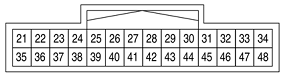
| 53 | G | Parking brake signal Parking brake is applied. 0 V Parking brake is released. 4.5 V |
| 55 | W | Composite image signalground |
| 56 | B | Composite image signal |
| 57 | BG | I-Key memory |
| 58 | G | AV-ACC (DCM) |
| 59 | shield | Microphone signal shield |
| 60 | W | Microphone voltage Out (5V) |
| 61 | W | Communication signal(CONT→DISP) |
| 62 | P | CAN–L |
| 63 | LG | AV communication signal (L) |
| 64 | LG | AV communication signal (L) terminate |
| 67 | P | MR output |
| 68 | LG | Ignition signal |
| 69 | R | Reverse signal Selector lever is in R position. Battery voltage Selector lever is in other than R position. 0 V |
| 70 | BG | Vehicle speed signal (8-pulse) |
| 71 | shield | Composite image signal shield |
| 72 | R | Composite image synchro-nizing signal |
| 75 | B | Microphone signal |
| 76 | shield | Communication signal shield |
| 77 | B | Communication signal(DISP→CONT) |
| 78 | L | CAN–H |
| 79 | SB | AV communication signal (H) |
| 80 | SB | AV communication signal (H) terminate |
W/C stands for Wire Color. It is very dependent on model and model year.


| Pin Number |
W/C | Signal |
|---|---|---|
| 91 | W | Auxiliary image signal In |
| 92 | B | Auxiliary image signal ground |
| 94 | shield | Auxiliary image signal shield |
| 97 | Y | Disk eject signal |
| 98 | V | Switch ground |
| 105 | W | Composite image signalground |
| 106 | shield | Composite image signal shield |
| 107 | B | Composite image signal |
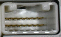
W/C stands for Wire Color. It is very dependent on model and model year.
| Pin Number |
W/C | Signal |
|---|---|---|
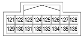
| 122 | B | Sound signal guide |
| 123 | W | Sound signal guide ground |
| 124 | B | Pre amp sound signal subwoofer |
| 125 | W | Pre amp sound signal center |
| 126 | Y | Pre amp sound signal shield |
| 131 | shield | Sound signal guide shield |
| 132 | W | Pre amp sound signal subwoofer ground |
| 133 | B | Pre amp sound signal center ground |
W/C stands for Wire Color. It is very dependent on model and model year.

| Pin Number |
W/C | Signal |
|---|---|---|
| 137 | W | VBUS signal (USB interface) |
| 138 | G | USB ground |
| 139 | L | USB D+ signal |
| 140 | R | USB D− signal |
| 141 | shield | USB shield |
W/C stands for Wire Color. It is very dependent on model and model year.
| Pin Number |
W/C | Signal |
|---|---|---|
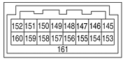
| 145 | B | USB D- signal (Telematics) |
| 146 | B | USB VBUS signal (Telematics) |
| 147 | W | Manufacturer specific signal (Telematics) |
| 151 | L | VOICE ground (Telematics) |
| 152 | W | U-VOICE signal (Telematics) |
| 153 | L/W | USB D+ signal (Telematics) |
| 154 | shield | USB ground |
| 160 | B | D-VOICE signal (Telematics) |
| 161 | shield | USB shield (Telematics) |
W/C stands for Wire Color. It is very dependent on model and model year.

| Pin Number |
W/C | Signal |
|---|---|---|
| 162 | shield | RGB digital image signal shield |
| 163 | shield | RGB digital image signal shield |
| 164 | B | RGB digital image signal(−) |
| 165 | B | RGB digital image signal(+) |

 correct
 incorrect