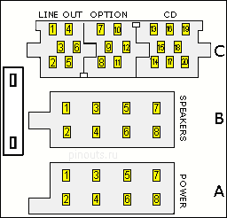
| A: Power | B: Speakers | C: Changer / special |
| 1.CAN B | First RR | First - |
| 2. BOSE IN | Second RR - | Second - |
| 3.CAN A | Third RF | Third - |
| 4. - | 4. RF - | 4. - |
| 5. antenna control | 5. LF | 5. - |
| 6. - | 6. LF - | 6. control BOSTER |
| 7. +12 V BATT | 7. LR | 7. Tel: AF + |
| 8. Ground (-) | 8. LR - | 8. Tel: AF- |
| Radio is connected only one plus, so do not turn off the ignition. |
|
9. Tel Mute |
| 10. RC-A | ||
| 11. RC-B | ||
| 12. mass | ||
| 13. DATA OUT | ||
| 14. DATA IN | ||
| 15. 12 V, not to exclude | ||
| 16. 12 V off | ||
| 17. mass | ||
| 18. Audio CD GND | ||
| 19. CD audio L | ||
| 20. Audio CD R | ||
| CD Changer Interface 13-20 |
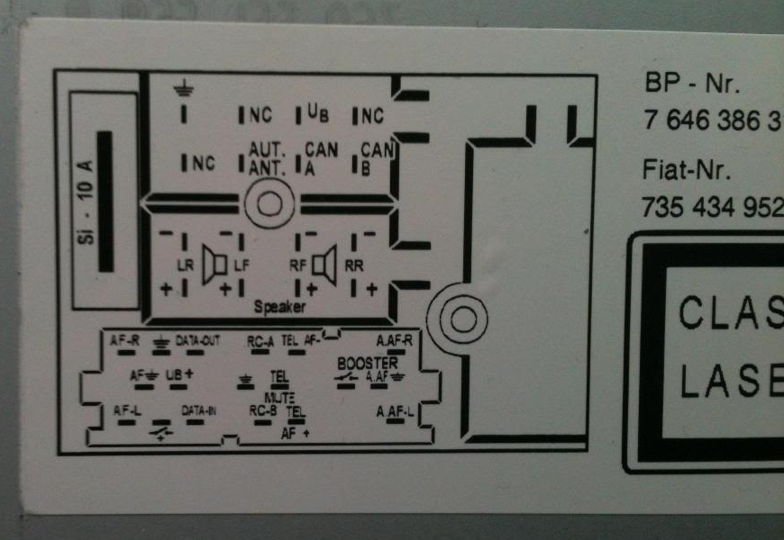
Changer connector looks like a standard Blaupunkt. Explanations may include CAN bus interface. It provides information about the signal speed, and is used to identify the car, if it is not connected to the radio will not turn on just shows CANCHECK.


 correct
 incorrect