
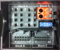
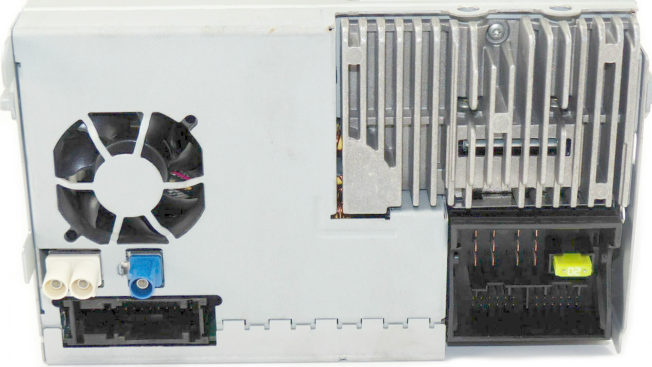
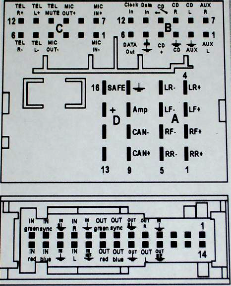
Multi-pin connector A, 8-pin, for loudspeaker outputs
| Pin | Function |
|---|---|
| 1 | Rear right loudspeaker, positive |
| 2 | Front right loudspeaker, positive |
| 3 | Front left loudspeaker, positive |
| 4 | Rear left loudspeaker, positive |
| 5 | Rear right loudspeaker, negative |
| 6 | Front right loudspeaker, negative |
| 7 | Front left loudspeaker, negative |
| 8 | Rear left loudspeaker, negative |
Multi-pin connector A, 8-pin, for voltage supply lines and CAN bus
| Pin | Function |
|---|---|
| 9 | CAN bus, high |
| 10 | CAN bus, low |
| 11 | Display voltage supply, positive, optional only on the Low radio version |
| 12 | Voltage supply, negative, terminal 31 |
| 13 | Display HS CAN bus low, optional only on the Low radio version, not for Midline |
| 14 | Display HS CAN bus high, optional only on the Low radio version, not for Midline |
| 15 | Voltage supply, positive, terminal 30 |
| 16 | Anti-theft coding control signal, SAFE, positive |
Multi-pin connector B, 12-pin, for CD changer control and CD audio input signals
| Pin | Function |
|---|---|
| 1 | Left input AUX signals |
| 2 | AUX signal ground |
| 3 | CD changer, audio signal ground |
| 4 | CD changer, voltage supply, positive, terminal 30, contact continuous power handling greater than 1A, short-term peak power handling 5A |
| 6 | CD changer, DATA OUT (data exchange for CD changer control from radio navigation system to CD changer) |
| 7 | Right input AUX signals |
| 8 | CD changer, left audio channel, CD/L |
| 9 | CD changer, right audio channel, CD/R |
| 10 | CD changer, control line, switched positive |
| 11 | CD changer, DATA IN (data exchange for CD changer control from CD changer to radio navigation system) |
| 12 | CD changer, CLOCK (internal check protocol for data flow monitoring) |
Multi-pin connector C, 12-pin, for telephone and microphone signals
| Pin | Function |
|---|---|
| 1 | Microphone input, negative |
| 2 | AUX output, audio, right |
| 3 | AUX output, common signal ground |
| 4 | Microphone output, minus |
| 5 | Left telephone audio input signal, negative |
| 6 | Right telephone audio input signal, negative |
| 7 | Microphone input, positive |
| 8 | AUX output, audio, left |
| 9 | Microphone output, positive |
| 10 | Telephone mute (radio mute) |
| 11 | Left telephone audio input signal, positive |
| 12 | Right telephone audio input signal, positive |
26-pin Connector
| Pin | Function |
|---|---|
| 4 | Video signals input, RGBS, negative |
| 6 | Internal universal cellular telephone preparation, handy detect |
| 7 | Internal universal cellular telephone preparation, cradle and description of key functions |
| 8 | Internal universal cellular telephone preparation, cradle, antenna diagnosis |
| 9 | Video signals input, RGBS, negative |
| 10 | Right video signal input NF |
| 11 | Video signal input, shielding mass |
| 12 | Video signal input, synchronization vertical and horizontal |
| 13 | Video signal input, green |
| 19 | Internal universal cellular telephone preparation, cradle, negative |
| 20 | Internal universal cellular telephone preparation, switched terminal 30 |
| 22 | Video signal input NF, negative |
| 23 | Left video signal input NF |
| 24 | Video signals input, RGBS, negative |
| 25 | Video signal input, blue |
| 26 | Video signal input, red |
| Pin Notation |
Pin function |
|---|---|
Power pins |
|
| + | Battery+ (12V direct from Battery). |
| GND, GROUND | Chassis Ground |
Audio pins |
|
| FR+ or RF+ | Front right speaker out |
| FL+ or LF+ | Front left speaker out |
| RR+ | Rear right speaker out |
| LR+ or RL+ | Rear left speaker out |
| FR- or RF-, FL- or LF-, RR-, LR- or RL-, SGND | The corresponding speaker ground |
| IN-R, IN-L | Audio line out |
| LINE IN | Audio line in |
Misc. pins |
|
| TEL MUTE | This pin is used to silence the audio, earthed by some other external components that is connected to the radio. |
| CAN-L, CAN-H | CAN on board diagnostic bus |
| CD-IN L+, CD-IN L-, CD-IN R+, CD-IN R-, CL, CH, IH, CDL, CDR | CD-changer audio |
 correct
 incorrect