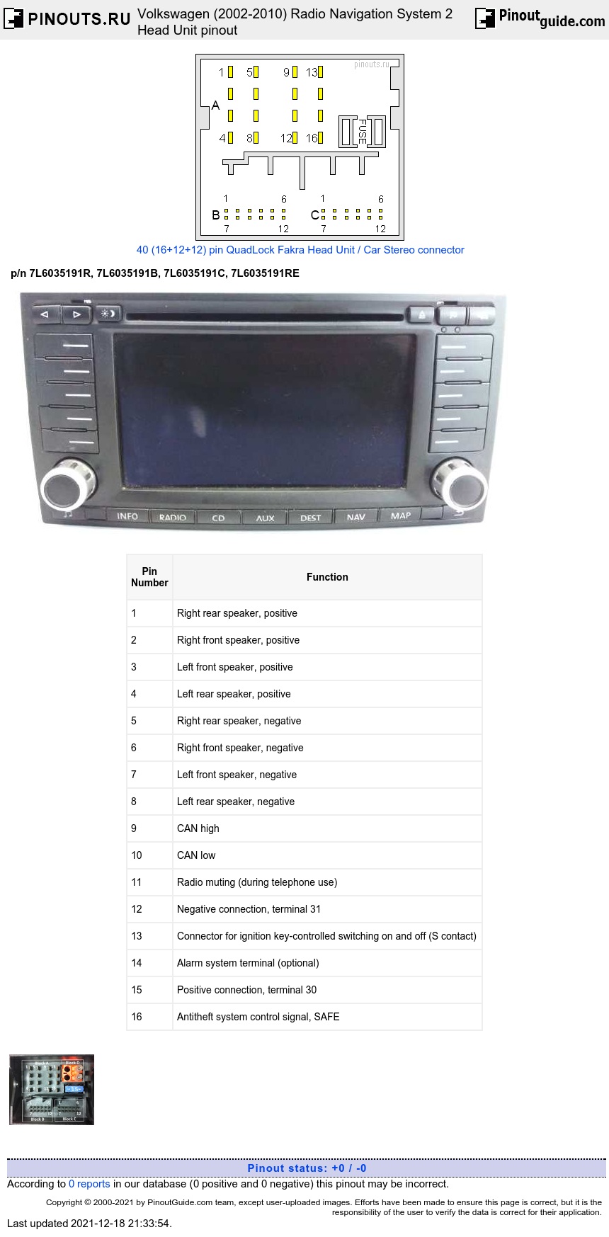
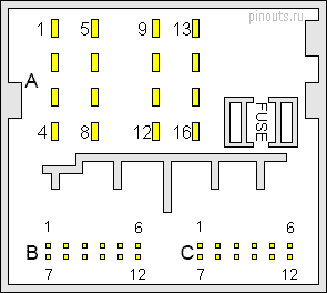
16 pin Main Audio Connector
| Pin Number |
Function |
|---|---|
| 1 | Right rear speaker, positive |
| 2 | Right front speaker, positive |
| 3 | Left front speaker, positive |
| 4 | Left rear speaker, positive |
| 5 | Right rear speaker, negative |
| 6 | Right front speaker, negative |
| 7 | Left front speaker, negative |
| 8 | Left rear speaker, negative |
| 9 | CAN high |
| 10 | CAN low |
| 11 | Radio muting (during telephone use) |
| 12 | Negative connection, terminal 31 |
| 13 | Connector for ignition key-controlled switching on and off (S contact) |
| 14 | Alarm system terminal (optional) |
| 15 | Positive connection, terminal 30 |
| 16 | Antitheft system control signal, SAFE |
12 pin connector C
| Pin Number |
Function |
|---|---|
| 1 | External audio output, left |
| 2 | External audio input ground |
| 3 | Line out, left |
| 5 | Driving directions low frequency (+) |
| 6 | Telephone audio signal input, negative |
| 7 | External audio input, right |
| 8 | Line out, ground |
| 9 | Line out, right |
| 11 | Driving directions low frequency (-) |
| 12 | Telephone audio signal input, positive |
12 pin B connector
| Pin Number |
Function |
|---|---|
| 1 | Headphone audio signal output, right, positive |
| 2 | CD changer, left and right port, ground |
| 3 | Headphone audio signal output, right, negative |
| 4 | CD changer, voltage supply, positive |
| 6 | CD changer, data out bus (data exchange for CD changer control from radio navigation system to CD changer) |
| 8 | CD changer, left port audio, positive |
| 9 | CD changer, right port audio, positive |
| 10 | CD Changer, control signal |
| 11 | CD changer, data in bus (data exchange for CD changer control from CD changer to radio navigation system) |
| 12 | CD changer, clock bus (internal test protocol for monitoring data flow) |
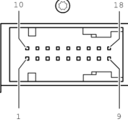
18 pin connector
| Pin Number |
Function |
|---|---|
| 2 | Audio signal ground |
| 3 | Audio signal ground |
| 4 | Shielding ground |
| 5 | Video signal ground |
| 6 | Video switching signal |
| 7 | Video signal ground |
| 8 | Video signal ground |
| 9 | Video signal ground |
| 11 | Audio signal, left |
| 12 | Audio signal, right |
| 13 | Shielding ground |
| 14 | Synchronization of vertical and horizontal picture signals |
| 15 | 50 Hertz/60 Hertz |
| 16 | Signal input for picture signal blue |
| 17 | Signal input for picture signal green |
| 18 | Signal input for picture signal red |


 correct
 incorrect