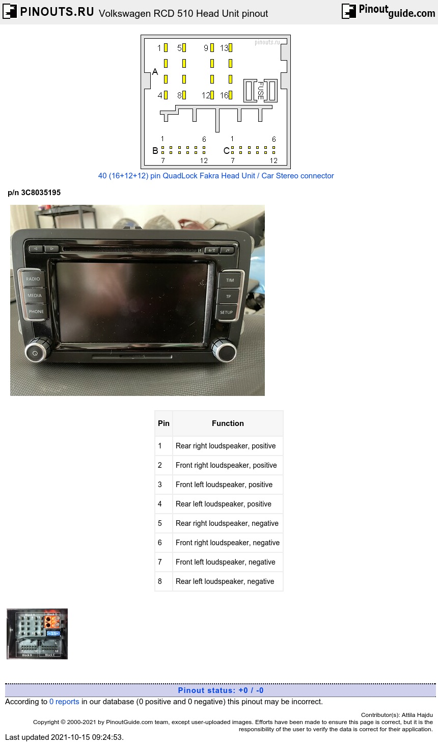
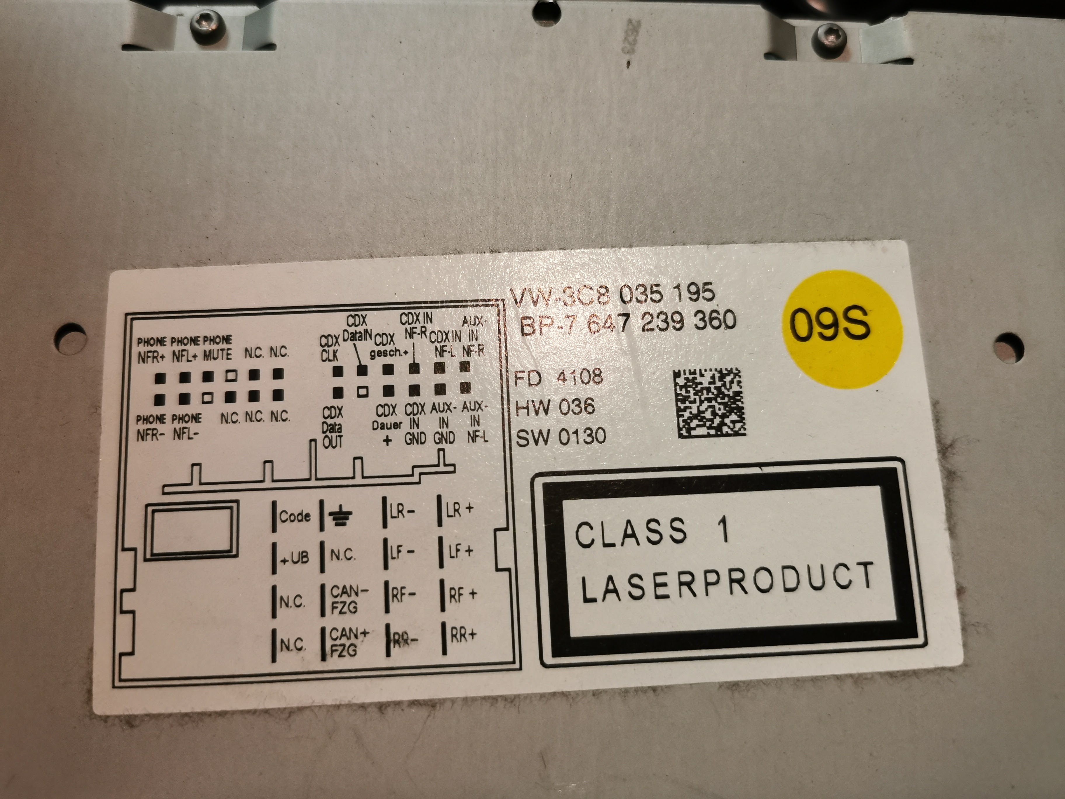
Multi-pin connector A, 8-pin, for loudspeaker outputs
| Pin | Function |
|---|---|
| 1 | Rear right loudspeaker, positive |
| 2 | Front right loudspeaker, positive |
| 3 | Front left loudspeaker, positive |
| 4 | Rear left loudspeaker, positive |
| 5 | Rear right loudspeaker, negative |
| 6 | Front right loudspeaker, negative |
| 7 | Front left loudspeaker, negative |
| 8 | Rear left loudspeaker, negative |
Multi-pin connector A, 8-pin, for voltage supply lines and CAN bus
| Pin | Function |
|---|---|
| 9 | CAN bus, high |
| 10 | CAN bus, low |
| 11 | N.C. |
| 12 | Voltage supply, negative, terminal 31 |
| 13 | N.C. |
| 14 | N.C. |
| 15 | Voltage supply, positive, terminal 30 |
| 16 | Anti-theft coding control signal, SAFE, positive |
Multi-pin connector B, 12-pin, for CD changer control and CD audio input signals
| Pin | Function |
|---|---|
| 1 | Left input AUX signals |
| 2 | AUX signal ground |
| 3 | CD changer, audio signal ground |
| 4 | CD changer, voltage supply, positive, terminal 30, contact continuous power handling greater than 1A, short-term peak power handling 5A |
| 6 | CD changer, DATA OUT (data exchange for CD changer control from radio navigation system to CD changer) |
| 7 | Right input AUX signals |
| 8 | CD changer, left audio channel, CD/L |
| 9 | CD changer, right audio channel, CD/R |
| 10 | CD changer, control line, switched positive |
| 11 | CD changer, DATA IN (data exchange for CD changer control from CD changer to radio navigation system) |
| 12 | CD changer, CLOCK (internal check protocol for data flow monitoring) |
Multi-pin connector C, 12-pin, for telephone signals
| Pin | Function |
|---|---|
| 1 | N.C. |
| 2 | N.C. |
| 3 | N.C. |
| 4 | N.C. |
| 5 | Left telephone audio input signal, negative |
| 6 | Right telephone audio input signal, negative |
| 7 | N.C. |
| 8 | N.C. |
| 9 | N.C. |
| 10 | Telephone mute (radio mute) |
| 11 | Left telephone audio input signal, positive |
| 12 | Right telephone audio input signal, positive |
 correct
 incorrect