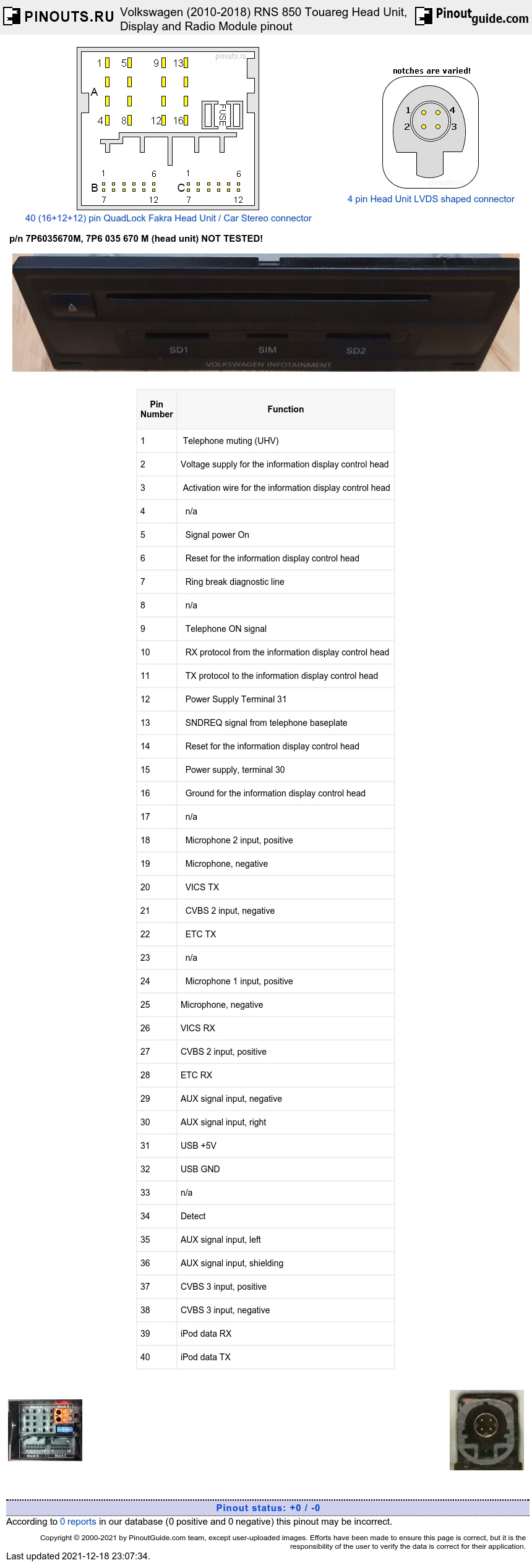
Multi-pin Main Connector
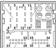
| Pin Number |
Function |
|---|---|
| 1 | Telephone muting (UHV) |
| 2 | Voltage supply for the information display control head |
| 3 | Activation wire for the information display control head |
| 4 | n/a |
| 5 | Signal power On |
| 6 | Reset for the information display control head |
| 7 | Ring break diagnostic line |
| 8 | n/a |
| 9 | Telephone ON signal |
| 10 | RX protocol from the information display control head |
| 11 | TX protocol to the information display control head |
| 12 | Power Supply Terminal 31 |
| 13 | SNDREQ signal from telephone baseplate |
| 14 | Reset for the information display control head |
| 15 | Power supply, terminal 30 |
| 16 | Ground for the information display control head |
| 17 | n/a |
| 18 | Microphone 2 input, positive |
| 19 | Microphone, negative |
| 20 | VICS TX |
| 21 | CVBS 2 input, negative |
| 22 | ETC TX |
| 23 | n/a |
| 24 | Microphone 1 input, positive |
| 25 | Microphone, negative |
| 26 | VICS RX |
| 27 | CVBS 2 input, positive |
| 28 | ETC RX |
| 29 | AUX signal input, negative |
| 30 | AUX signal input, right |
| 31 | USB +5V |
| 32 | USB GND |
| 33 | n/a |
| 34 | Detect |
| 35 | AUX signal input, left |
| 36 | AUX signal input, shielding |
| 37 | CVBS 3 input, positive |
| 38 | CVBS 3 input, negative |
| 39 | iPod data RX |
| 40 | iPod data TX |
Gray 4-pin Connector
| Pin Number |
Function |
|---|---|
| 1 | LVDS- |
| 4 | LIN |
| 3 | LVDS+ |
| 2 | GND |
Yellow 4-pin Connector
| Pin Number |
Function |
|---|---|
| 1 | USB D+ |
| 4 | iPod recognized |
| 3 | USB D- |
| 2 | GND |
20 pin Connector at the display Unit p/n 7P6919603J, 7P6 919 603 J

| Pin Number |
Function |
|---|---|
| 1 | Screening |
| 2 | Version 0 |
| 3 | Version 1 |
| 4,5,9,10,19,20 | n/a |
| 6 | Activation Wire |
| 7 | Power supply, terminal 30 |
| 8 | Power supply, terminal 31 |
| 11 | LED 1 on the 3-button module (Emergency Call Button) |
| 12 | LED 1 on the 3-button module (Emergency Call Button) |
| 13 | Reset BT-MU |
| 14 | Reset MU-BT |
| 15 | RxD |
| 16 | TxD |
| 17 | Button input, 3-button module (emergency call button) |
| 18 | Button output, 3-button module (emergency call button) |
Multi-pin connector at the Radio Module p/n 4G0035061S, 4G0 035 061 S
| Pin Number |
Description |
|---|---|
| 1 | Right Rear Speaker, Positive |
| 2 | Right Front Speaker, Positive |
| 3 | Left Front Speaker, Positive |
| 4 | Left Rear Speaker, Positive |
| 5 | Right Rear Speaker, Negative |
| 6 | Right Front Speaker, Negative |
| 7 | Left Front Speaker, Negative |
| 8 | Left Rear Speaker, Negative |
| 9 | Speaker subwoofer, positive |
| 10 | Center speaker, positive |
| 11 | Diag Speaker/ Ring-Break Diagnostic Cable |
| 12 | n/a |
| 13 | Speaker subwoofer, negative |
| 14 | Center speaker, negative |
| 15,16 | n/a |
| 17 | AUX IN left |
| 18 | AUX IN LR |
| 19 | AUX IN diag |
| 20 | n/a |
| 21 | Telephone in, diag |
| 22 | Telephone in, negative |
| 23 | AUX in, right |
| 24 | AUX in, shielding |
| 25,26 | n/a |
| 27 | Telephone in, shielding |
| 28 | Telephone in, positive |
| 29 | Headphones 1, diag. |
| 30 | n/a |
| 31 | Headphones 1 and 2, diag. |
| 32,33 | n/a |
| 34 | Headphones 2, diag. |
| 35 | Headphones 1, left |
| 36 | Headphones 1, left and right |
| 37 | Headphones 1, right |
| 38 | Headphones 2, left |
| 39 | Headphones 2, left and right |
| 40 | Headphones 2, right |
| 41 | Power Supply terminal 31 |
| 42 | Power supply, terminal 30 |
Also for
7P6035670 7P6 035 670
7P6035670A 7P6 035 670 A
7P6035670AX 7P6 035 670 AX
7P6035670B 7P6 035 670 B
7P6035670BX 7P6 035 670 BX
7P6035670C 7P6 035 670 C
7P6035670CX 7P6 035 670 CX
7P6035670D 7P6 035 670 D
7P6035670DX 7P6 035 670 DX
7P6035670E 7P6 035 670 E
7P6035670EX 7P6 035 670 EX
7P6035670F 7P6 035 670 F
7P6035670FX 7P6 035 670 FX
7P6035670K 7P6 035 670 K
 correct
 incorrect