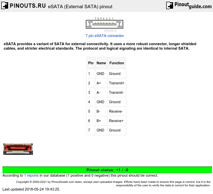
eSATA was standardized in 2004, with specifically defined cables, connectors, and signal requirements for external SATA drives. eSATA features full SATA speed for external disks, no protocol conversion from IDE/SATA to USB/Firewire, cable length up to 2m.
eSATA pinout diagram
| Pin | Name | Function |
|---|---|---|
| 1 | GND | Ground |
| 2 | A+ | Transmit+ |
| 3 | A- | Transmit- |
| 4 | GND | Ground |
| 5 | B- | Receive- |
| 6 | B+ | Receive+ |
| 7 | GND | Ground |
Transmit pins are connected to Receive pins on the other side. Pin 1 may be used on Hot Plug arrays for signalling.
The protocol and logical signaling (link/transport layers and above) are identical to internal SATA. The differences are:
Minimum transmit amplitude increased: Range is 500–600 mV instead of 400–600 mV. Minimum receive amplitude decreased: Range is 240–600 mV instead of 325–600 mV. Maximum cable length increased to 2 metres from 1 metre.
The eSATA cable and connector is similar to the SATA 1.0a cable and connector, with these exceptions:
The eSATA connector is mechanically different to prevent unshielded internal cables from being used externally.
The eSATA insertion depth is deeper: 6.6 mm instead of 5 mm. The contact positions are also changed.
The eSATA cable has an extra shield to reduce EMI to FCC and CE requirements.
The eSATA connector uses metal springs for shield contact and mechanical retention.
SATA does not provide power, which means that external 2.5 disks which would otherwise be powered over the USB or Firewire cable need a separate power cable when connected over eSATA.


 correct
 incorrect