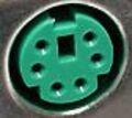
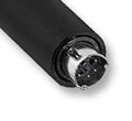
The PCs keyboard implements a bi-directional protocol. The keyboard can send data (so called scan codes, unique for each button - one for button pressed, another for button released) to the Host and the Host can send data to the Keyboard. The keyboard is free to send data to the host when both the KBD Data and KBD Clock lines are high (Idle). The KBD Clock line can be used as a Clear to Send line. If the host takes the KBD Clock line low, the keyboard will buffer any data until the KBD Clock is released, ie goes high. Should the Host take the KBD Data line low, then the keyboard will prepare to accept a command from the host.
The transmission of data in the forward direction, ie Keyboard to Host is done with a frame of 11 bits. The first bit is a Start Bit (Logic 0) followed by 8 data bits (LSB First), one Parity Bit (Odd Parity) and a Stop Bit (Logic 1). The Keyboard will generate the clock, typical frequency of the clock signal ranges from 20 to 30 Khz.
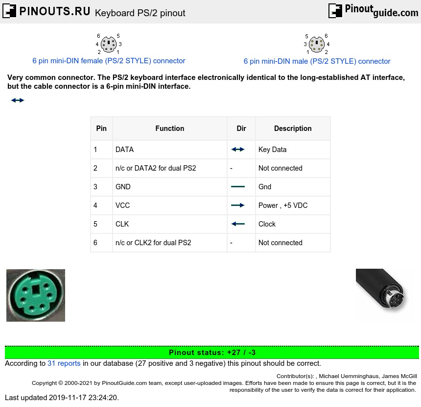
| Pin | Function | Dir | Description |
|---|---|---|---|
| 1 | DATA |  |
Key Data |
| 2 | n/c or DATA2 for dual PS2 | - | Not connected |
| 3 | GND |  |
Gnd |
| 4 | VCC |  |
Power , +5 VDC |
| 5 | CLK |  |
Clock |
| 6 | n/c or CLK2 for dual PS2 | - | Not connected |
The keyboard and auxiliary device signals are driven by open-collector drivers pulled to 5Vdc through a pull-up resistor.
Sink current Max: 20mA ;
Hi-level output V Min 5.0 Vdc minus pull-up ;
Low-level Output v Max 0.5 Vdc;
High-level input v Min 2.0 Vdc;
Low-level input v Max 0.8 Vdc.
Note: Direction is Computer relative Keyboard.


 correct
 incorrect