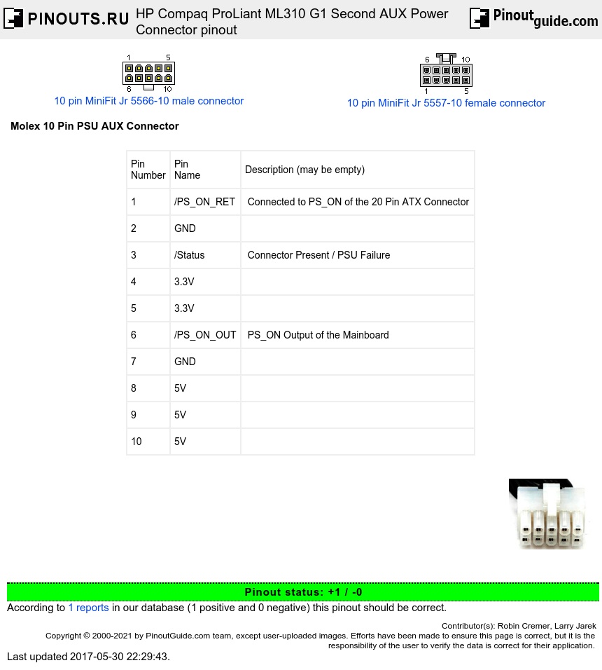
This is the Second AUX Power Connector Pinout for the Proliant ML310 Generation 1, may be compatible to other Proliant Servers and ML310 Generations.
It uses an 10 Pin Molex-Connector, the pin keying equates the first 5x2-Pins half of the 20 Pin ATX Power Connector.
The only special lines are Pin 1 (PS_ON_RETURN), Pin 3 (Status) and Pin 6 (PS_ON_OUT).
Pin 3 is tied to ground if the connector is present / the PSU is O.K. Pin 6 is the Power Management Circuit's PS_ON Output, Pin 1 is connected to the normal PS_ON of the 20 Pin ATX Connector, so only if Pin 1 and 6 are bridged, the Mainboard is able to turn on the PSU, otherwise the signal doesn't reach Pin 14 of the 20 Pin ATX Connector.
| Pin Number |
Pin Name |
Description (may be empty) |
| 1 | /PS_ON_RET | Connected to PS_ON of the 20 Pin ATX Connector |
| 2 | GND | |
| 3 | /Status | Connector Present / PSU Failure |
| 4 | 3.3V | |
| 5 | 3.3V | |
| 6 | /PS_ON_OUT | PS_ON Output of the Mainboard |
| 7 | GND | |
| 8 | 5V | |
| 9 | 5V | |
| 10 | 5V |
Apart from this special connector, the ML310 G1 Mainboard uses a 20 Pin ATX Power Connector and a 4 Pin 12V Auxilliary Connector, both with standard wiring.
If you plan to connect a standard ATX PSU to this Mainboard, only Pin 1, 3 and 6 need to be taken care of by bridging them as described. The additional Power Rails are connected in parallel to the 20 Pin ATX ones, so if your 20 Pin ATX connector is able to handle this load (which can't be much, the original PSU had 300 Watts in total), e.g. has sufficient AWG / conductor diameter, it works flawlessly.

 correct
 incorrect