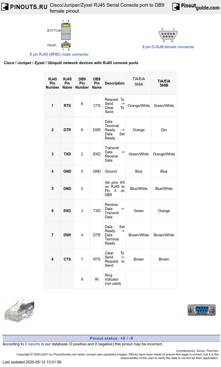
Network devices with RJ45 console ports typically follow the Cisco pin out. The pinout below shows a null modem wiring between the RJ45 and the DB9 female connector. This is known to work on Cisco, Juniper, Zyxel and Ubiquiti Edge series devices with RJ45 console ports. If you are using UTP network cable then colour coding
| RJ45 Pin Number |
RJ45 Pin Name |
DB9 Pin Number | DB9 Pin Name | Description |
TIA/EIA |
TIA/EIA 568B |
|---|---|---|---|---|---|---|
| 1 | RTS |
8 |
CTS | Request To Send -> Clear To Send | Orange/White | Green/White |
| 2 | DTR | 6 | DSR | Data Terminal Ready -> Data Set Ready | Orange | Grn |
| 3 | TXD | 2 | RXD | Transmit Data -> Receive Data | Green/White | Orange/White |
| 4 | GND | 5 | GND | Ground | Blue | Blue |
| 5 | GND | 5 | (tie pins 4/5 on RJ45 to Pin 5 on DB9 | Blue/White | Blue/White | |
| 6 | RXD | 3 | TXD | Receive Data <- Transmit Data | Green | Orange |
| 7 | DSR | 4 | DTR | Data Set Ready -> Data Terminal Ready | Brown/White | Brown/White |
| 8 | CTS | 7 | RTS | Clear To Send <- Request to Send | Brown | Brown |
| 9 | RI | Ring Indicator (not used) |
A simplified version of this NULL modem cable would only connect RXD, TXD and GND (this sacrifices flow control for simplicity). For other variations on null modem cables see this page
| RJ45 Pin Number |
RJ45 Pin Name |
DB9 Pin Number | DB9 Pin Name | Description |
TIA/EIA |
TIA/EIA 568B |
|---|---|---|---|---|---|---|
| 3 | TXD | 2 | RXD | Transmit Data -> Receive Data | Green/White | Orange/White |
| 5 | GND | 5 | GND | Ground | Blue/White | Blue/White |
| 6 | RXD | 3 | TXD | Receive Data <- Transmit Data | Green | Orange |


 correct
 incorrect