Most newer printers are equipped with IEEE1284-B or USB interfaces
| Pin | Name | Dir | Description |
|---|---|---|---|
| 1 | /STROBE | Strobe | |
| 2 | D0 | Data Bit 0 | |
| 3 | D1 | Data Bit 1 | |
| 4 | D2 | Data Bit 2 | |
| 5 | D3 | Data Bit 3 | |
| 6 | D4 | Data Bit 4 | |
| 7 | D5 | Data Bit 5 | |
| 8 | D6 | Data Bit 6 | |
| 9 | D7 | Data Bit 7 | |
| 10 | /ACK | Acknowledge | |
| 11 | BUSY | Busy | |
| 12 | POUT | Paper Out | |
| 13 | SEL | Select | |
| 14 | /AUTOFEED | Autofeed | |
| 15 | n/c | - | Not used |
| 16 | 0 V | Logic Ground | |
| 17 | CHASSIS GND | Shield Ground | |
| 18 | +5 V PULLUP | +5 V DC (50 mA max) | |
| 19 | GND | Signal Ground (Strobe Ground) | |
| 20 | GND | Signal Ground (Data 0 Ground) | |
| 21 | GND | Signal Ground (Data 1 Ground) | |
| 22 | GND | Signal Ground (Data 2 Ground) | |
| 23 | GND | Signal Ground (Data 3 Ground) | |
| 24 | GND | Signal Ground (Data 4 Ground) | |
| 25 | GND | Signal Ground (Data 5 Ground) | |
| 26 | GND | Signal Ground (Data 6 Ground) | |
| 27 | GND | Signal Ground (Data 7 Ground) | |
| 28 | GND | Signal Ground (Acknowledge Ground) | |
| 29 | GND | Signal Ground (Busy Ground) | |
| 30 | /GNDRESET | Reset Ground | |
| 31 | /RESET | Reset | |
| 32 | /FAULT | Fault (Low when offline) | |
| 33 | 0 V | Signal Ground | |
| 34 | n/c | - | Not used |
| 35 | +5 V | +5 V DC | |
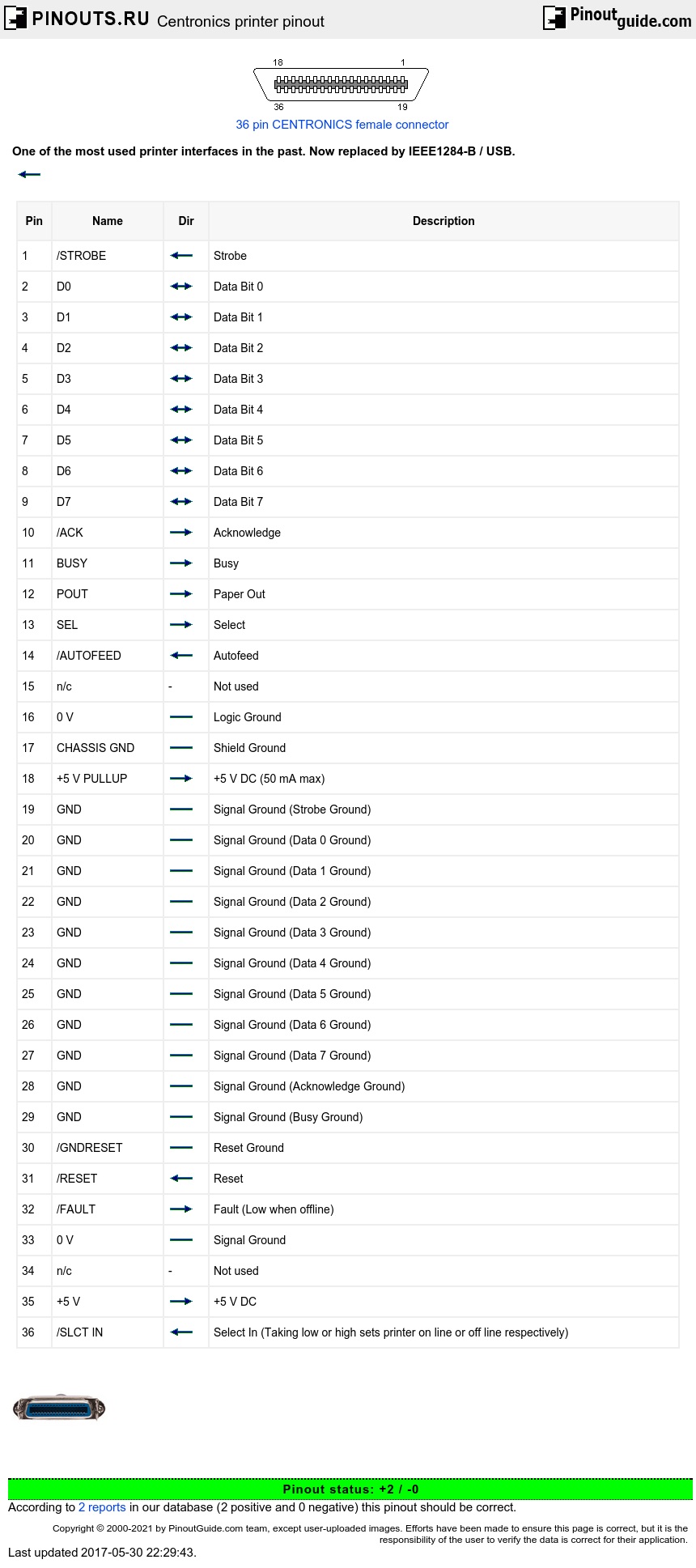
| 36 | /SLCT IN | Select In (Taking low or high sets printer on line or off line respectively) |
Functional Description
| STROBE: | Active low pulse used to transfer data into the printer. | Pulse with must be between 0.5 and 500 microseconds for most printers. |
|---|---|---|
| Dn: | Data lines, high is a one. | |
| ACK: | Active low pulse indicates that data has been received and the printer is ready to accept more. | |
| BUSY: | A high signal indicates that the printer cannot receive data. | |
| PE: | A high signal indicates that the printer is out of paper (Paper End) | |
| SELECT OUT: | A high signal indicates that the printer is on-line | |
| AUTO FEED: | A low signal indicates to the printer that a line feed is required after each Carriage return. | This signal is used as a ground line by some manufacturers. |
| OSCXT: | A 100-200 KHz signal used by true Centronics printers only. | |
| +5V: | +5Vdc | Not provided by all manufacturers |
| PRIME: | A low signal resets the printer to its power-up state and the printer buffer is cleared | |
| FAULT: | A low signal indicates that the printer is in an off-line or error state | |
| LINE COUNT: | Used by true Centronics printers only. | Most of the time not used |
| SELECT IN: | A high signal indicates to the printer that a DC1/ DC3 code is valid. | This signal is used by a few manufacturers |
 correct
 incorrect