| Pin |
Signal |
Abbr. |
Source |
| 1 |
Data Strobe (low) |
STROBE |
Computer |
| 2 |
Data Bit 1 (LSB) |
D1 |
Computer |
| 3 |
Data Bit 2 |
D2 |
Computer |
| 4 |
Data Bit 3 |
D3 |
Computer |
| 5 |
Data Bit 4 |
D4 |
Computer |
| 6 |
Data Bit 5 |
D5 |
Computer |
| 7 |
Data Bit 6 |
D6 |
Computer |
| 8 |
Data Bit 7 |
D7 |
Computer |
| 9 |
Data Bit 8 (MSB) |
D8 |
Computer |
| 10 |
Acknowledge (low) |
ACK |
Printer |
| 11 |
Busy (high) |
BUSY |
Printer |
| 12 |
Paper End (high) |
PE |
Printer |
| 13 |
Select (high) |
SEL |
Printer |
| 14 |
Supply Ground |
? |
- |
| 15 |
Oscillator Transmit |
? |
Printer |
| 16 |
Logical Ground |
? |
- |
| 17 |
Chassis Ground |
? |
- |
| 18 |
+5 Vdc |
+V |
Printer |
| 19 |
Return Data Strobe |
? |
- |
| 20 |
Return Data Bit 1 |
? |
- |
| 21 |
Return Data Bit 2 |
? |
- |
| 22 |
Return Data Bit 3 |
? |
- |
| 23 |
Return Data Bit 4 |
? |
- |
| 24 |
Return Data Bit 5 |
? |
- |
| 25 |
Return Data Bit 6 |
? |
- |
| 26 |
Return Data Bit 7 |
? |
- |
| 27 |
Return Data Bit 8 |
? |
- |
| 28 |
Return ACK |
? |
- |
| 29 |
Return BUSY |
? |
- |
| 30 |
Return Input Prime |
? |
- |
| 31 |
Input Prime (low) |
? |
Computer |
| 32 |
Fault (low) |
FAULT |
Printer |
| 33 |
- |
- |
- |
| 34 |
- |
- |
- |
| 35 |
- |
- |
- |
| 36 |
- |
- |
- |
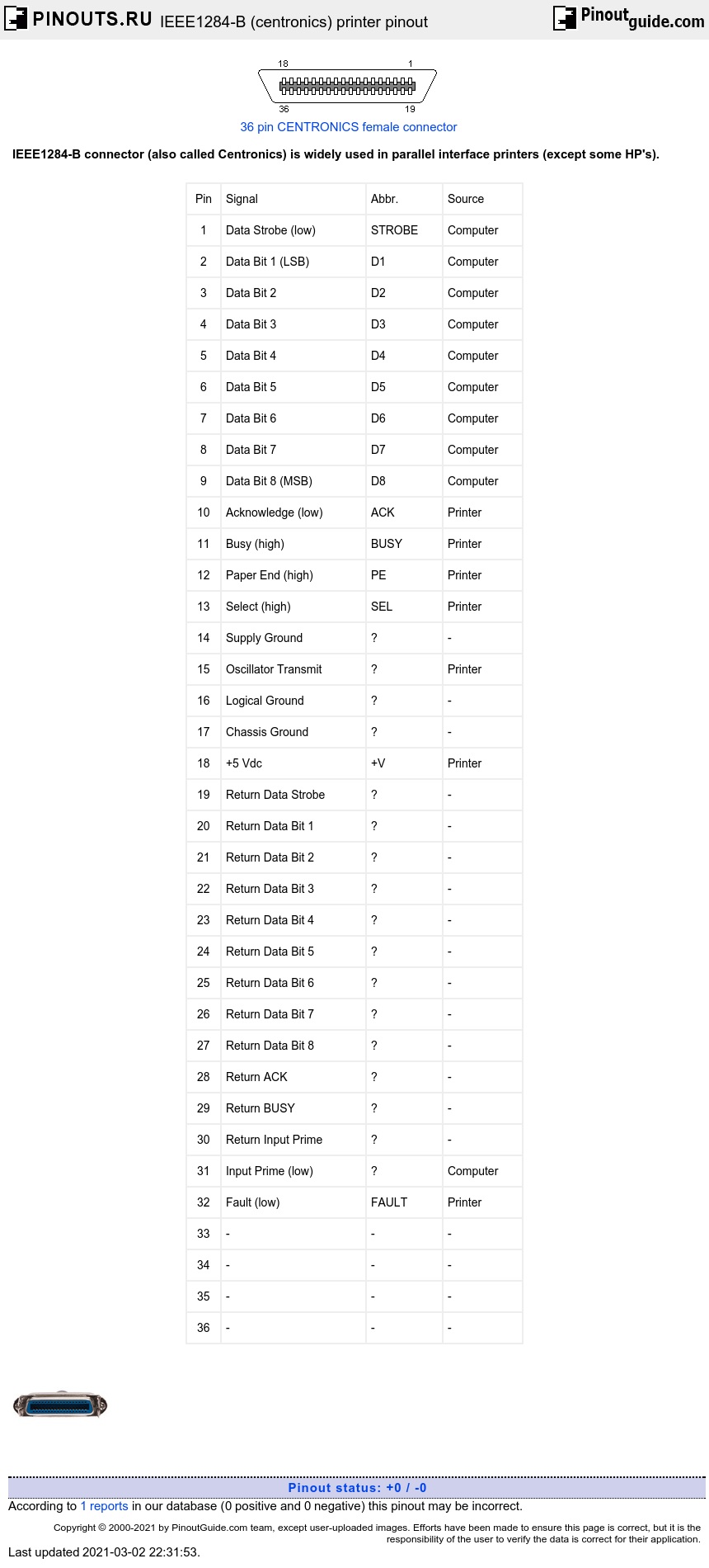
| STROBE |
Active low pulse used to transfer data into the printer. |
Pulse with must be between 0.5 and 500 microseconds for most printers. |
| ACK |
Active low pulse indicates that data has been received and the printer is ready to accept more. |
? |
| BUSY |
A high signal indicates that the printer cannot receive data. |
? |
| PE |
A high signal indicates that the printer is out of paper (Paper End) |
? |
| SELECT OUT |
A high signal indicates that the printer is on-line |
? |
| AUTO FEED |
A low signal indicates to the printer that a line feed is required after each Carriage return. |
This signal is used as a ground line by some manufacturers. |
| OSCXT |
A 100-200 KHz signal used by true Centronics printers only. |
? |
| +5V |
+5Vdc |
Not provided by all manufacturers |
| PRIME |
A low signal resets the printer to its power-up state and the printer buffer is cleared |
? |
| FAULT |
A low signal indicates that the printer is in an off-line or error state |
? |
| LINE COUNT |
Used by true Centronics printers only. |
Most of the time not used |
| LINE COUNT |
See 34 |
? |
| SELECT IN |
A high signal indicates to the printer that a DC1/ DC3 code is valid. |
This signal is used by a few manufacturers |
| Host Logic High |
A high signal indicates that the host is alive (turned on). |
Specific IEEE 1284 signal. |
| Peripheral Logic High |
A high signal indicates that the peripheral (printer) is alive (turned on). |
Specific IEEE 1284 signal. |
IEEE-1284 standard specifies, among other things, five modes of data transfer: standard (legacy style), reverse (nibble and byte modes), and half-duplex or bidirectional (EPP and ECP). It also details cable properties and connector types. The 1284 standard is an innovation that allows parallel printer ports to transfer data at many times the standard speed, and also allows for an array of bidirectional communications and longer cable runs. The Enhanced Parallel Port (EPP) and Extended Capabilities Port (ECP) both follow 1284 standards, although EPP was developed prior to 1284's release. The primary advantage of this technology is the ability to use devices on a PC's parallel port that were previously unable to be used because of communication limitations. However, printers have also benefited and Hewlett-Packards Bitronix protocol, introduced with their LasetJet 4, is proof. Bitronix takes advantage of 1284's nibble mode, and allows data to be sent from the printer to the computer quickly in this manner.

 correct
 incorrect