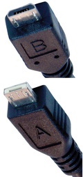
| Micro Pin # | Pin Name |
Description | Standard Receptacle Pin # |
|---|---|---|---|
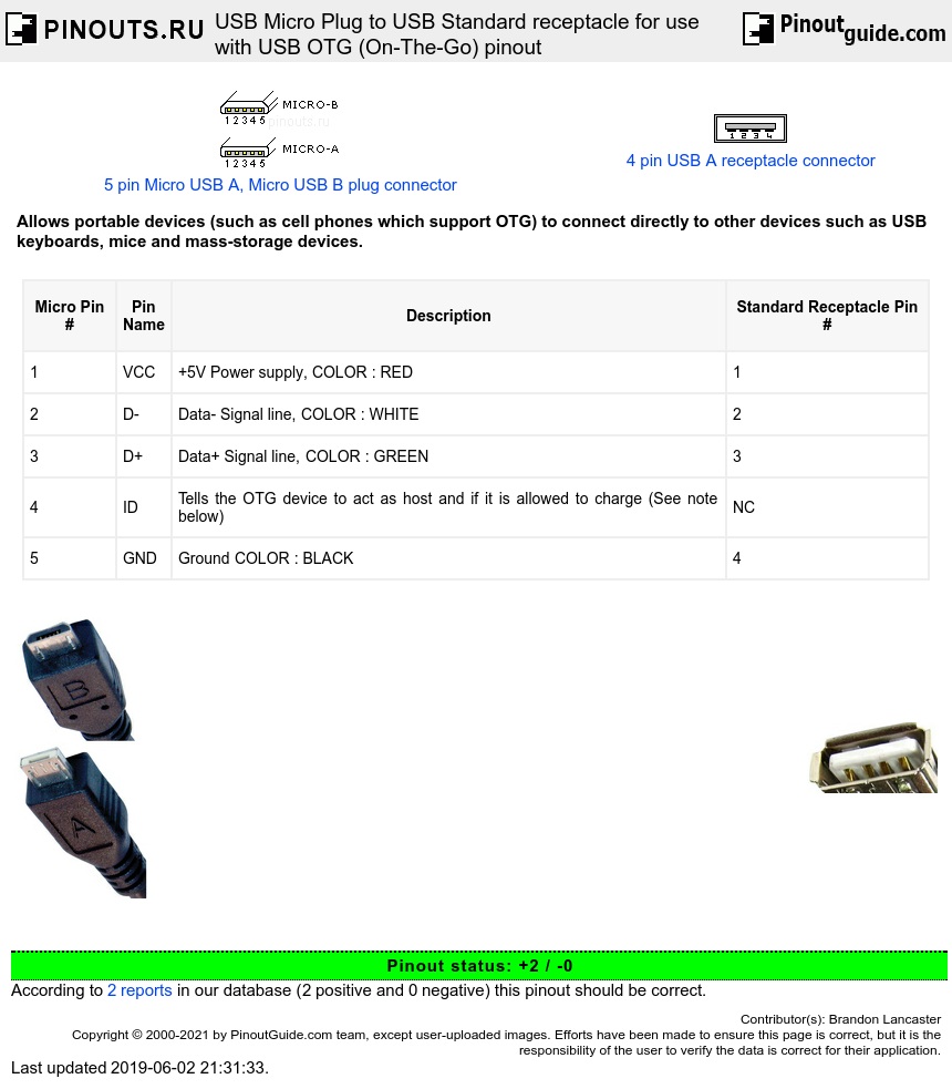
| 1 | VCC | +5V Power supply, COLOR : RED | 1 |
| 2 | D- | Data- Signal line, COLOR : WHITE | 2 |
| 3 | D+ | Data+ Signal line, COLOR : GREEN | 3 |
| 4 | ID | Tells the OTG device to act as host and if it is allowed to charge (See note below) | NC |
| 5 | GND | Ground COLOR : BLACK | 4 |
Note-The ID pin can be directly connected to ground. This will tell the OTG device that it can not charge (and hence must supply current to VCC) but should act as a USB host. The ID pin can also have a 124 kΩ impedence to ground (see below). This will tell the OTG device that it is allowed to draw current off VCC (e.g. charge its battery) as well as act as a USB host.
The 124 kΩ mode is slightly more complicated to wire: place a 124 kΩ resistor between ID and GND. Attach proper ends of a regulated 5 V charger to VCC and GND. Attach a 10-100 nF capacitor between VCC and GND. Be sure that the charger is connected, otherwise both the OTG device and slave device will try and draw current from VCC without a source. The infomation in this paragraph was inferred as the simplest way to construct an accessory charger adapter as specified in the Battery Charging Specification, Revision 1.2 from www.usb.org website. It has not been tested.
Also note that on the slave side, it is not standard to have a USB B standard recepticle. Only USB A standard recepticle should be used.


 correct
 incorrect