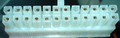
| Pin | Signal | Description |
| 1 | +3.3 VDC | |
| 2 | +3.3 VDC | |
| 3 | COM | |
| 4 | +5 VDC | |
| 5 | COM | |
| 6 | +5 VDC | |
| 7 | COM | |
| 8 | PWR_OK | Power good - indicate that VDC voltages are in range. |
| 9 | +5 VSB | Standby voltage |
| 10 | +12 VDC | |
| 11 | +12 VDC | |
| 12 | +3.3 VDC | |
| 13 | +3.3 VDC | |
| 14 | -12 VDC | |
| 15 | COM | |
| 16 | PS_ON# | Active low. TTL compatible (0.1-0.8V low; 2.0 high?). When low - DC outputs are enabled. When high - power supply should not deliver DC current. |
| 17 | COM | |
| 18 | COM | |
| 19 | COM | |
| 20 | N/C | |
| 21 | +5 VDC | |
| 22 | +5 VDC | |
| 23 | +5 VDC | |
| 24 | COM |
 correct
 incorrect
If you did publish instruction for Do-It-Yourself device with this pinout, share the link with us.