
PCI Universal Card 32/64 bit
 ----------------------------------------------------------------
|    PCI         Component Side (side B)                         |
|                                                                |
|                                                                |
|                                                optional        |
|    ____     mandatory 32-bit pins            64-bit pins  _____|
|___|    |||||||--|||||||||||||||||--|||||||--||||||||||||||
         ^     ^  ^               ^  ^     ^  ^            ^
       b01   b11  b14           b49  b52 b62  b63          b94
PCI 5V Card 32/64 bit
|                                                optional        |
|    ____     mandatory 32-bit pins            64-bit pins  _____|
|___|    ||||||||||||||||||||||||||--|||||||--||||||||||||||
PCI 3.3V Card 32/64 bit
|                                                optional        |
|    ____     mandatory 32-bit pins            64-bit pins  _____|
|___|    |||||||--||||||||||||||||||||||||||--||||||||||||||
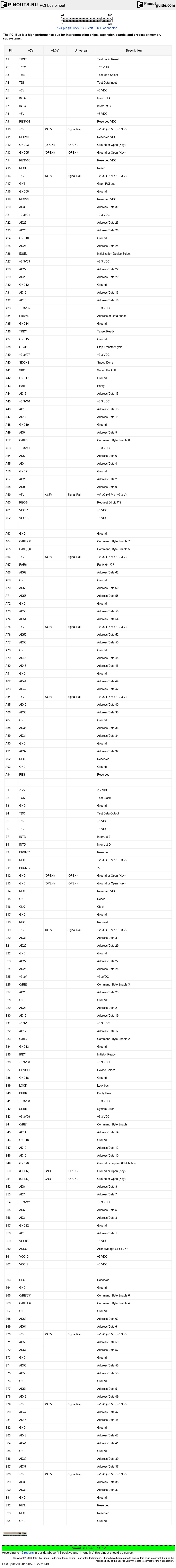
The PCI specification defines two types of connectors that may be implemented at the system board level: One for systems that implement 5 Volt signaling levels, and one for systems that implement 3.3 Volt signaling levels. In addition, PCI systems may implement either the 32-bit or 64-bit connector. Most PCI buses implement only the 32-bit portion of the connector which consists of pins 1 through 62. Advanced systems which support 64-bit data transfers implement the full PCI bus connector which consists of pins 1 through 94. Three types of add-in boards may be implemented: 5 Volt add-in boards include a key notch in pin positions 50 and 51 to allow them to be plugged only into 5 Volt system connectors. 3.3 Volt add-in boards include a key notch in pin positions 12 and 13 to allow them to be plugged only into 3.3 Volt system connectors. Universal add-in boards include both key notches to allow them to be plugged into either 5 Volt or 3.3 Volt system connectors.
Universal PCI Bus Pinouts
                    Rear of Computer
                    :------:------:
               -12V |- B1     A1 -| Test Reset
         Test Clock |- B2     A2 -| +12V
             Ground |- B3     A3 -| Test Mode Select
   Test Data Output |- B4     A4 -| Test Data Input
                +5V |- B5     A5 -| +5V
                +5V |- B6     A6 -| Interrupt A
        Interrupt B |- B7     A7 -| Interrupt C
        Interrupt D |- B8     A8 -| +5V
            PRSNT1# |- B9     A9 -| Reserved
           Reserved |- B10   A10 -| +V I/O
            PRSNT2# |- B11   A11 -| Reserved
                    :------:------:
                    :------:------:
           Reserved |- B14   A14 -| Reserved
             Ground |- B15   A15 -| Reset
              Clock |- B16   A16 -| +V I/O
             Ground |- B17   A17 -| Grant
            Request |- B18   A18 -| Ground
             +V I/O |- B19   A19 -| Reserved
         Address 31 |- B20   A20 -| Address 30
         Address 29 |- B21   A21 -| +3.3V
             Ground |- B22   A22 -| Address 28
         Address 27 |- B23   A23 -| Address 26
         Address 25 |- B24   A24 -| Ground
              +3.3V |- B25   A25 -| Address 24
             C/BE 3 |- B26   A26 -| Init Device Select
         Address 23 |- B27   A27 -| +3.3V
             Ground |- B28   A28 -| Address 22
         Address 21 |- B29   A29 -| Address 20
         Address 19 |- B30   A30 -| Ground
              +3.3V |- B31   A31 -| Address 18
         Address 17 |- B32   A32 -| Address 16
             C/BE 2 |- B33   A33 -| +3.3V
             Ground |- B34   A34 -| Cycle Frame
    Initiator Ready |- B35   A35 -| Ground
              +3.3V |- B36   A36 -| Target Ready
      Device Select |- B37   A37 -| Ground
             Ground |- B38   A38 -| Stop
               Lock |- B39   A39 -| +3.3V
       Parity Error |- B40   A40 -| Snoop Done
              +3.3V |- B41   A41 -| Snoop Backoff
       System Error |- B42   A42 -| Ground
              +3.3V |- B43   A43 -| PAR
             C/BE 1 |- B44   A44 -| Address 15
         Address 14 |- B45   A45 -| +3.3V
       M66EN/Ground |- B46   A46 -| Address 13
         Address 12 |- B47   A47 -| Address 11
         Address 10 |- B48   A48 -| Ground
             Ground |- B49   A49 -| Address 9
                    :------:------:
                    :------:------:
          Address 8 |- B52   A52 -| C/BE 0
          Address 7 |- B53   A53 -| +3.3V
              +3.3V |- B54   A54 -| Address 6
          Address 5 |- B55   A55 -| Address 4
          Address 3 |- B56   A56 -| Ground
             Ground |- B57   A57 -| Address 2
          Address 1 |- B58   A58 -| Address 0
             +5 I/O |- B59   A59 -| +V I/O
 Acknowledge 64-bit |- B60   A60 -| Request 64-bit
                +5V |- B61   A61 -| +5V
                +5V |- B62   A62 -| +5V
                    :------:------:
                    :------:------:
           Reserved |- B63   A63 -| Ground
             Ground |- B64   A64 -| C/BE 7
             C/BE 6 |- B65   A65 -| C/BE 5
             C/BE 4 |- B66   A66 -| +V I/O
             Ground |- B67   A67 -| Parity 64-bit
         Address 63 |- B68   A68 -| Address 62
          Address 61|- B69   A69 -| Ground
             +V I/O |- B70   A70 -| Address 60
         Address 59 |- B71   A71 -| Address 58
         Address 57 |- B72   A72 -| Ground
             Ground |- B73   A73 -| Address 56
         Address 55 |- B74   A74 -| Address 54
         Address 53 |- B75   A75 -| +V I/O
             Ground |- B76   A76 -| Address 52
         Address 51 |- B77   A77 -| Address 50
         Address 49 |- B78   A78 -| Ground
             +V I/O |- B79   A79 -| Address 48
         Address 47 |- B80   A80 -| Address 46
         Address 45 |- B81   A81 -| Ground
             Ground |- B82   A82 -| Address 44
         Address 43 |- B83   A83 -| Address 42
         Address 41 |- B84   A84 -| +V I/O
             Ground |- B85   A85 -| Address 40
         Address 39 |- B86   A86 -| Address 38
         Address 37 |- B87   A87 -| Ground
             +V I/O |- B88   A88 -| Address 36
         Address 35 |- B89   A89 -| Address 34
         Address 33 |- B90   A90 -| Ground
             Ground |- B91   A91 -| Address 32
           Reserved |- B92   A92 -| Reserved
           Reserved |- B93   A93 -| Ground
             Ground |- B94   A94 -| Reserved
                    :------:------:
Same with descriptions:
| Pin | +5V | +3.3V | Universal | Description |
|---|---|---|---|---|
| A1 | TRST | Test Logic Reset | ||
| A2 | +12V | +12 VDC | ||
| A3 | TMS | Test Mde Select | ||
| A4 | TDI | Test Data Input | ||
| A5 | +5V | +5 VDC | ||
| A6 | INTA | Interrupt A | ||
| A7 | INTC | Interrupt C | ||
| A8 | +5V | +5 VDC | ||
| A9 | RESV01 | Reserved VDC | ||
| A10 | +5V | +3.3V | Signal Rail | +V I/O (+5 V or +3.3 V) |
| A11 | RESV03 | Reserved VDC | ||
| A12 | GND03 | (OPEN) | (OPEN) | Ground or Open (Key) |
| A13 | GND05 | (OPEN) | (OPEN) | Ground or Open (Key) |
| A14 | RESV05 | Reserved VDC | ||
| A15 | RESET | Reset | ||
| A16 | +5V | +3.3V | Signal Rail | +V I/O (+5 V or +3.3 V) |
| A17 | GNT | Grant PCI use | ||
| A18 | GND08 | Ground | ||
| A19 | RESV06 | Reserved VDC | ||
| A20 | AD30 | Address/Data 30 | ||
| A21 | +3.3V01 | +3.3 VDC | ||
| A22 | AD28 | Address/Data 28 | ||
| A23 | AD26 | Address/Data 26 | ||
| A24 | GND10 | Ground | ||
| A25 | AD24 | Address/Data 24 | ||
| A26 | IDSEL | Initialization Device Select | ||
| A27 | +3.3V03 | +3.3 VDC | ||
| A28 | AD22 | Address/Data 22 | ||
| A29 | AD20 | Address/Data 20 | ||
| A30 | GND12 | Ground | ||
| A31 | AD18 | Address/Data 18 | ||
| A32 | AD16 | Address/Data 16 | ||
| A33 | +3.3V05 | +3.3 VDC | ||
| A34 | FRAME | Address or Data phase | ||
| A35 | GND14 | Ground | ||
| A36 | TRDY | Target Ready | ||
| A37 | GND15 | Ground | ||
| A38 | STOP | Stop Transfer Cycle | ||
| A39 | +3.3V07 | +3.3 VDC | ||
| A40 | SDONE | Snoop Done | ||
| A41 | SBO | Snoop Backoff | ||
| A42 | GND17 | Ground | ||
| A43 | PAR | Parity | ||
| A44 | AD15 | Address/Data 15 | ||
| A45 | +3.3V10 | +3.3 VDC | ||
| A46 | AD13 | Address/Data 13 | ||
| A47 | AD11 | Address/Data 11 | ||
| A48 | GND19 | Ground | ||
| A49 | AD9 | Address/Data 9 | ||
| A52 | C/BE0 | Command, Byte Enable 0 | ||
| A53 | +3.3V11 | +3.3 VDC | ||
| A54 | AD6 | Address/Data 6 | ||
| A55 | AD4 | Address/Data 4 | ||
| A56 | GND21 | Ground | ||
| A57 | AD2 | Address/Data 2 | ||
| A58 | AD0 | Address/Data 0 | ||
| A59 | +5V | +3.3V | Signal Rail | +V I/O (+5 V or +3.3 V) |
| A60 | REQ64 | Request 64 bit ??? | ||
| A61 | VCC11 | +5 VDC | ||
| A62 | VCC13 | +5 VDC | ||
| A63 | GND | Ground | ||
| A64 | C/BE[7]# | Command, Byte Enable 7 | ||
| A65 | C/BE[5]# | Command, Byte Enable 5 | ||
| A66 | +5V | +3.3V | Signal Rail | +V I/O (+5 V or +3.3 V) |
| A67 | PAR64 | Parity 64 ??? | ||
| A68 | AD62 | Address/Data 62 | ||
| A69 | GND | Ground | ||
| A70 | AD60 | Address/Data 60 | ||
| A71 | AD58 | Address/Data 58 | ||
| A72 | GND | Ground | ||
| A73 | AD56 | Address/Data 56 | ||
| A74 | AD54 | Address/Data 54 | ||
| A75 | +5V | +3.3V | Signal Rail | +V I/O (+5 V or +3.3 V) |
| A76 | AD52 | Address/Data 52 | ||
| A77 | AD50 | Address/Data 50 | ||
| A78 | GND | Ground | ||
| A79 | AD48 | Address/Data 48 | ||
| A80 | AD46 | Address/Data 46 | ||
| A81 | GND | Ground | ||
| A82 | AD44 | Address/Data 44 | ||
| A83 | AD42 | Address/Data 42 | ||
| A84 | +5V | +3.3V | Signal Rail | +V I/O (+5 V or +3.3 V) |
| A85 | AD40 | Address/Data 40 | ||
| A86 | AD38 | Address/Data 38 | ||
| A87 | GND | Ground | ||
| A88 | AD36 | Address/Data 36 | ||
| A89 | AD34 | Address/Data 34 | ||
| A90 | GND | Ground | ||
| A91 | AD32 | Address/Data 32 | ||
| A92 | RES | Reserved | ||
| A93 | GND | Ground | ||
| A94 | RES | Reserved | ||
| B1 | -12V | -12 VDC | ||
| B2 | TCK | Test Clock | ||
| B3 | GND | Ground | ||
| B4 | TDO | Test Data Output | ||
| B5 | +5V | +5 VDC | ||
| B6 | +5V | +5 VDC | ||
| B7 | INTB | Interrupt B | ||
| B8 | INTD | Interrupt D | ||
| B9 | PRSNT1 | Reserved | ||
| B10 | RES | +V I/O (+5 V or +3.3 V) | ||
| B11 | PRSNT2 | ?? | ||
| B12 | GND | (OPEN) | (OPEN) | Ground or Open (Key) |
| B13 | GND | (OPEN) | (OPEN) | Ground or Open (Key) |
| B14 | RES | Reserved VDC | ||
| B15 | GND | Reset | ||
| B16 | CLK | Clock | ||
| B17 | GND | Ground | ||
| B18 | REQ | Request | ||
| B19 | +5V | +3.3V | Signal Rail | +V I/O (+5 V or +3.3 V) |
| B20 | AD31 | Address/Data 31 | ||
| B21 | AD29 | Address/Data 29 | ||
| B22 | GND | Ground | ||
| B23 | AD27 | Address/Data 27 | ||
| B24 | AD25 | Address/Data 25 | ||
| B25 | +3.3V | +3.3VDC | ||
| B26 | C/BE3 | Command, Byte Enable 3 | ||
| B27 | AD23 | Address/Data 23 | ||
| B28 | GND | Ground | ||
| B29 | AD21 | Address/Data 21 | ||
| B30 | AD19 | Address/Data 19 | ||
| B31 | +3.3V | +3.3 VDC | ||
| B32 | AD17 | Address/Data 17 | ||
| B33 | C/BE2 | Command, Byte Enable 2 | ||
| B34 | GND13 | Ground | ||
| B35 | IRDY | Initiator Ready | ||
| B36 | +3.3V06 | +3.3 VDC | ||
| B37 | DEVSEL | Device Select | ||
| B38 | GND16 | Ground | ||
| B39 | LOCK | Lock bus | ||
| B40 | PERR | Parity Error | ||
| B41 | +3.3V08 | +3.3 VDC | ||
| B42 | SERR | System Error | ||
| B43 | +3.3V09 | +3.3 VDC | ||
| B44 | C/BE1 | Command, Byte Enable 1 | ||
| B45 | AD14 | Address/Data 14 | ||
| B46 | GND18 | Ground | ||
| B47 | AD12 | Address/Data 12 | ||
| B48 | AD10 | Address/Data 10 | ||
| B49 | GND20 | Ground or request 66MHz bus | ||
| B50 | (OPEN) | GND | (OPEN) | Ground or Open (Key) |
| B51 | (OPEN) | GND | (OPEN) | Ground or Open (Key) |
| B52 | AD8 | Address/Data 8 | ||
| B53 | AD7 | Address/Data 7 | ||
| B54 | +3.3V12 | +3.3 VDC | ||
| B55 | AD5 | Address/Data 5 | ||
| B56 | AD3 | Address/Data 3 | ||
| B57 | GND22 | Ground | ||
| B58 | AD1 | Address/Data 1 | ||
| B59 | VCC08 | +5 VDC | ||
| B60 | ACK64 | Acknowledge 64 bit ??? | ||
| B61 | VCC10 | +5 VDC | ||
| B62 | VCC12 | +5 VDC | ||
| B63 | RES | Reserved | ||
| B64 | GND | Ground | ||
| B65 | C/BE[6]# | Command, Byte Enable 6 | ||
| B66 | C/BE[4]# | Command, Byte Enable 4 | ||
| B67 | GND | Ground | ||
| B68 | AD63 | Address/Data 63 | ||
| B69 | AD61 | Address/Data 61 | ||
| B70 | +5V | +3.3V | Signal Rail | +V I/O (+5 V or +3.3 V) |
| B71 | AD59 | Address/Data 59 | ||
| B72 | AD57 | Address/Data 57 | ||
| B73 | GND | Ground | ||
| B74 | AD55 | Address/Data 55 | ||
| B75 | AD53 | Address/Data 53 | ||
| B76 | GND | Ground | ||
| B77 | AD51 | Address/Data 51 | ||
| B78 | AD49 | Address/Data 49 | ||
| B79 | +5V | +3.3V | Signal Rail | +V I/O (+5 V or +3.3 V) |
| B80 | AD47 | Address/Data 47 | ||
| B81 | AD45 | Address/Data 45 | ||
| B82 | GND | Ground | ||
| B83 | AD43 | Address/Data 43 | ||
| B84 | AD41 | Address/Data 41 | ||
| B85 | GND | Ground | ||
| B86 | AD39 | Address/Data 39 | ||
| B87 | AD37 | Address/Data 37 | ||
| B88 | +5V | +3.3V | Signal Rail | +V I/O (+5 V or +3.3 V) |
| B89 | AD35 | Address/Data 35 | ||
| B90 | AD33 | Address/Data 33 | ||
| B91 | GND | Ground | ||
| B92 | RES | Reserved | ||
| B93 | RES | Reserved | ||
| B94 | GND | Ground |
Notes: Pin 63-94 exists only on 64 bit PCI implementations.
+V I/O is 3.3V on 3.3V boards, 5V on 5V boards, and define signal rails on the Universal board.
PCI is a synchronous bus architecture with all data transfers being performed relative to a system clock (CLK). The initial PCI specification permitted a maximum clock rate of 33 MHz allowing one bus transfer to be performed every 30 nanoseconds. Later, Revision 2.1 of the PCI specification extended the bus definition to support operation at 66 MHz, but the vast majority of todays personal computers continue to implement a PCI bus that runs at a maximum speed of 33 MHz.
PCI implements a 32-bit multiplexed Address and Data bus (AD[31:0]). It architects a means of supporting a 64-bit data bus through a longer connector slot, but most of todays personal computers support only 32-bit data transfers through the base 32-bit PCI connector. At 33 MHz, a 32-bit slot supports a maximum data transfer rate of 132 MBytes/sec, and a 64-bit slot supports 264 MBytes/sec.
The multiplexed Address and Data bus allows a reduced pin count on the PCI connector that enables lower cost and smaller package size for PCI components. Typical 32-bit PCI add-in boards use only about 50 signals pins on the PCI connector of which 32 are the multiplexed Address and Data bus. PCI bus cycles are initiated by driving an address onto the AD[31:0] signals during the first clock edge called the address phase. The address phase is signaled by the activation of the FRAME# signal. The next clock edge begins the first of one or more data phases in which data is transferred over the AD[31:0] signals.
In PCI terminology, data is transferred between an initiator which is the bus master, and a target which is the bus slave. The initiator drives the C/BE[3:0]# signals during the address phase to signal the type of transfer (memory read, memory write, I/O read, I/O write, etc.). During data phases the C/BE[3:0]# signals serve as byte enable to indicate which data bytes are valid. Both the initiator and target may insert wait states into the data transfer by deasserting the IRDY# and TRDY# signals. Valid data transfers occur on each clock edge in which both IRDY# and TRDY# are asserted.
A PCI bus transfer consists of one address phase and any number of data phases. I/O operations that access registers within PCI targets typically have only a single data phase. Memory transfers that move blocks of data consist of multiple data phases that read or write multiple consecutive memory locations. Both the initiator and target may terminate a bus transfer sequence at any time. The initiator signals completion of the bus transfer by deasserting the FRAME# signal during the last data phase. A target may terminate a bus transfer by asserting the STOP# signal. When the initiator detects an active STOP# signal, it must terminate the current bus transfer and re-arbitrate for the bus before continuing. If STOP# is asserted without any data phases completing, the target has issued a retry. If STOP# is asserted after one or more data phases have successfully completed, the target has issued a disconnect.
Initiators arbitrate for ownership of the bus by asserting a REQ# signal to a central arbiter. The arbiter grants ownership of the bus by asserting the GNT# signal. REQ# and GNT# are unique on a per slot basis allowing the arbiter to implement a bus fairness algorithm. Arbitration in PCI is hidden in the sense that it does not consume clock cycles. The current initiators bus transfers are overlapped with the arbitration process that determines the next owner of the bus.
PCI supports a rigorous auto configuration mechanism. Each PCI device includes a set of configuration registers that allow identification of the type of device (SCSI, video, Ethernet, etc.) and the company that produced it. Other registers allow configuration of the devices I/O addresses, memory addresses, interrupt levels, etc.
Although it is not widely implemented, PCI supports 64-bit addressing. Unlike the 64-bit data bus option which requires a longer connector with an additional 32-bits of data signals, 64-bit addressing can be supported through the base 32-bit connector. Dual Address Cycles are issued in which the low order 32-bits of the address are driven onto the AD[31:0] signals during the first address phase, and the high order 32-bits of the address (if non-zero) are driven onto the AD[31:0] signals during a second address phase. The remainder of the transfer continues like a normal bus transfer.
PCI defines support for both 5 Volt and 3.3 Volt signaling levels. The PCI connector defines pin locations for both the 5 Volt and 3.3 Volt levels. However, most early PCI systems were 5 Volt only, and did not provide active power on the 3.3 Volt connector pins. Over time more use of the 3.3 Volt interface is expected, but add-in boards which must work in older legacy systems are restricted to using only the 5 Volt supply. A keying scheme is implemented in the PCI connectors to prevent inserting an add-in board into a system with incompatible supply voltage.
Although used most extensively in PC compatible systems, the PCI bus architecture is processor independent. PCI signal definitions are generic allowing the bus to be used in systems based on other processor families.
PCI includes strict specifications to ensure the signal quality required for operation at 33 and 66 MHz. Components and add-in boards must include unique bus drivers that are specifically designed for use in a PCI bus environment. Typical TTL devices used in previous bus implementations such as ISA and EISA are not compliant with the requirements of PCI. This restriction along with the high bus speed dictates that most PCI devices are implemented as custom ASICs.
The higher speed of PCI limits the number of expansion slots on a single bus to no more than 3 or 4, as compared to 6 or 7 for earlier bus architectures. To permit expansion buses with more than 3 or 4 slots, the PCI SIG has defined a PCI-to-PCI Bridge mechanism. PCI-to-PCI Bridges are ASICs that electrically isolate two PCI buses while allowing bus transfers to be forwarded from one bus to another. Each bridge device has a primary PCI bus and a secondary PCI bus. Multiple bridge devices may be cascaded to create a system with many PCI buses.
This section is currently based solely on the work by Mark Sokos.
This file is not intended to be a thorough coverage of the PCI standard. It is for informational purposes only, and is intended to give designers and hobbyists an overview of the bus so that they might be able to design their own PCI cards. Thus, I/O operations are explained in the most detail, while memory operations, which will usually not be dealt with by an I/O card, are only briefly explained. Hobbyists are also warned that, due to the higher clock speeds involved, PCI cards are more difficult to design than ISA cards or cards for other slower busses. Many companies are now making PCI prototyping cards, and, for those fortunate enough to have access to FPGA programmers, companies like Xilinx are offering PCI compliant designs which you can use as a starting point for your own projects.
Signal Descriptions:
AD(x)
Address/Data Lines.
CLK
Clock. 33 MHz maximum.
C/BE(x)
Command, Byte Enable.
FRAME
Used to indicate whether the cycle is an address phase or a data phase.
DEVSEL
Device Select.
IDSEL
Initialization Device Select
INT(x)
Interrupt
IRDY
Initiator Ready
LOCK
Used to manage resource locks on the PCI bus.
M66EN
Ground when card runs in 33 MHz. Pulled high if card requests 66MHz bus. If all comonents (chipset and other cards) can run on 66MHz then PCI bus speed will be two times faster than on ordinary frequency. Defined since PCI 2.1 for 3.3v cards only.
REQ
Request. Requests a PCI transfer.
GNT
Grant. indicates that permission to use PCI is granted.
PAR
Parity. Used for AD0-31 and C/BE0-3.
PERR
Parity Error.
RST
Reset.
SBO
Snoop Backoff.
SDONE
Snoop Done.
SERR
System Error. Indicates an address parity error for special cycles or a system error.
STOP
Asserted by Target. Requests the master to stop the current transfer cycle.
TCK
Test Clock
TDI
Test Data Input
TDO
Test Data Output
TMS
Test Mode Select
TRDY
Target Ready
TRST
Test Logic Reset
The PCI bus treats all transfers as a burst operation. Each cycle begins with an address phase followed by one or more data phases. Data phases may repeat indefinitely, but are limited by a timer that defines the maximum amount of time that the PCI device may control the bus. This timer is set by the CPU as part of the configuration space. Each device has its own timer (see the Latency Timer in the configuration space).
The same lines are used for address and data. The command lines are also used for byte enable lines. This is done to reduce the overall number of pins on the PCI connector.
The Command lines (C/BE3 to C/BE0) indicate the type of bus transfer during the address phase.
| C/BE | Command Type |
|---|---|
| 0000 | Interrupt Acknowledge |
| 0001 | Special Cycle |
| 0010 | I/O Read |
| 0011 | I/O Write |
| 0100 | reserved |
| 0101 | reserved |
| 0110 | Memory Read |
| 0111 | Memory Write |
| 1000 | reserved |
| 1001 | reserved |
| 1010 | Configuration Read |
| 1011 | Configuration Write |
| 1100 | Multiple Memory Read |
| 1101 | Dual Address Cycle |
| 1110 | Memory-Read Line |
| 1111 | Memory Write and Invalidate |
The three basic types of transfers are I/O, Memory, and Configuration.
PCI timing diagrams:
            ___     ___     ___     ___     ___     ___
CLK     ___|   |___|   |___|   |___|   |___|   |___|   |___

        _______                                   _________
FRAME          |_________________________________|

                ______  _______  ______  ______  ______
AD      -------<______><_______><______><______><______>---
                Address  Data1    Data2   Data3   Data4

                ______  _______________________________
C/BE    -------<______><_______________________________>---
                Command   Byte Enable Signals

         ____________                                   ___
IRDY                 |_________________________________|

         _____________                                  ___
TRDY                  |________________________________|

         ______________                                 ___
DEVSEL                 |_______________________________|
PCI transfer cycle, 4 data phases, no wait states. Data is transferred on the rising edge of CLK.
                         [1]              [2]        [3]
            ___     ___     ___     ___     ___     ___     ___     ___
CLK     ___|   |___|   |___|   |___|   |___|   |___|   |___|   |___|   |__

        _______                                                  _________
FRAME          |________________________________________________|

                                   A               B               C
                ______           ______________  ______  _____________
AD      -------<______>---------<______________><______><_____________>---
                Address           Data1           Data2   Data3

                ______  ______________________________________________
C/BE    -------<______><______________________________________________>---
                Command   Byte Enable Signals

                                                         Wait
         ____________                                    _____         ___
IRDY                 |__________________________________|     |_______|

                        Wait            Wait
         ______________________         ______                         ___
TRDY                           |_______|      |_______________________|

         ______________                                                ___
DEVSEL                 |______________________________________________|
PCI transfer cycle, with wait states. Data is transferred on the rising edge of CLK at points labelled A, B, and C.
Bus Cycles:
Interrupt Acknowledge (0000)
The interrupt controller automatically recognizes and reacts to the INTA (interrupt acknowledge) command. In the data phase, it transfers the interrupt vector to the AD lines.
Special Cycle (0001)
| AD15-AD0 | Description |
|---|---|
| 0x0000 | Processor Shutdown |
| 0x0001 | Processor Halt |
| 0x0002 | x86 Specific Code |
| 0x0003 to 0xFFFF | Reserved |
I/O Read (0010) and I/O Write (0011)
Input/Output device read or write operation. The AD lines contain a byte address (AD0 and AD1 must be decoded). PCI I/O ports may be 8 or 16 bits. PCI allows 32 bits of address space. On IBM compatible machines, the Intel CPU is limited to 16 bits of I/O space, which is further limited by some ISA cards that may also be installed in the machine (many ISA cards only decode the lower 10 bits of address space, and thus mirror themselves throughout the 16 bit I/O space). This limit assumes that the machine supports ISA or EISA slots in addition to PCI slots.
The PCI configuration space may also be accessed through I/O ports 0x0CF8 (Address) and 0x0CFC (Data). The address port must be written first.
Memory Read (0110) and Memory Write (0111)
A read or write to the system memory space. The AD lines contain a doubleword address. AD0 and AD1 do not need to be decoded. The Byte Enable lines (C/BE) indicate which bytes are valid.
Configuration Read (1010) and Configuration Write (1011)
A read or write to the PCI device configuration space, which is 256 bytes in length. It is accessed in doubleword units. AD0 and AD1 contain 0, AD2-7 contain the doubleword address, AD8-10 are used for selecting the addressed unit a the malfunction unit, and the remaining AD lines are not used.
Address     Bit 32      16   15           0

00          Unit ID        | Manufacturer ID
04          Status         | Command
08          Class Code               | Revision
0C          BIST  | Header | Latency | CLS
10-24            Base Address Register
28          Reserved
2C          Reserved
30          Expansion ROM Base Address
34          Reserved
38          Reserved
3C          MaxLat|MnGNT   | INT-pin | INT-line
40-FF       available for PCI unit
Multiple Memory Read (1100)
This is an extension of the memory read bus cycle. It is used to read large blocks of memory without caching, which is beneficial for long sequential memory accesses.
Dual Address Cycle (1101)
Two address cycles are necessary when a 64 bit address is used, but only a 32 bit physical address exists. The least significant portion of the address is placed on the AD lines first, followed by the most significant 32 bits. The second address cycle also contains the command for the type of transfer (I/O, Memory, etc). The PCI bus supports a 64 bit I/O address space, although this is not available on Intel based PCs due to limitations of the CPU.
Memory-Read Line (1110)
This cycle is used to read in more than two 32 bit data blocks, typically up to the end of a cache line. It is more efficient than normal memory read bursts for a long series of sequential memory accesses.
Memory Write and Invalidate (1111)
This indicates that a minimum of one cache line is to be transferred. This allows main memory to be updated, saving a cache write-back cycle.
Sources: Inside the PCI Local Bus by Guy W. Kendall, Byte, February 1994 v 19 p. 177-180
Sources: The Indispensible PC Hardware Book by Hans-Peter Messmer, ISBN 0-201-8769-3
For a copy of the full PCI standard, contact:
PCI Special Interest Group (SIG)PO Box 14070
Portland, OR 97214
1-800-433-5177
1-503-797-4207
td/p/p
 correct
 incorrect