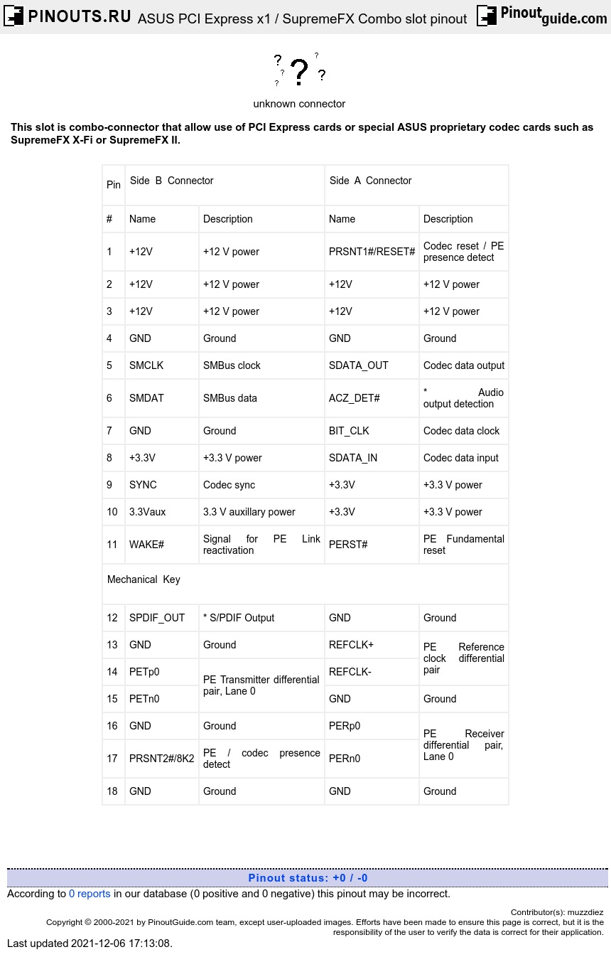
This interface is based on standard PCI Express x1 connector. Differences with standard PCIe x1 are highlighted with red.
The main principle looks most like AMR: generic audio interface resides on motherboard, and codec with all analog circuits is brought out to an expansion card. Although AMR interface was based on PCI-like 1.27mm-pitch connector, corresponding cards used AC97 codecs and was incompartible with PCI connectors, SupremeFX is based on PCIe 1.00mm-pitch connector, uses HDA codecs (something like ALC662, WM8850, WM8860, VT2021, etc), and may be used in special combo slot that supports PCIe cards.
Pin A1 is grounded by motherboard on standard PCIe slots; it brings codec to reset state if card is inserted into a non-combo slot. On a combo slot it should be ungrounded by motherboard circuitry if it detects a codec card, so codec will then start functioning.
Pin B17 (PRSNT2#/8K2) is tied up on a codec card to +12V through 8.2kOhm resistor. It is possible for motherboard circuitry to detect presence of codec cards using this pin.
Pins indicated by asterisk (A6 ACZ_DET#, B12 SPDIF_OUT) are found only on SupremeFX II Card; SupremeFX X-Fi has these pins unconnected (it has its own S/PDIF outputs).
Pins shown in gray (PE differential pairs, reset, wake, SMBus signals, and B7 GND) are not connected on SupremeFX cards. While pin B7 is not used by codec cards (even not connected to theirs ground plane), purpose of this is not unknown.
| Pin |
Side B Connector |
Side A Connector |
||
| # | Name | Description | Name | Description |
| 1 | +12V | +12 V power | PRSNT1#/RESET# | Codec reset / PE presence detect |
| 2 | +12V | +12 V power | +12V | +12 V power |
| 3 | +12V | +12 V power | +12V | +12 V power |
| 4 | GND | Ground | GND | Ground |
| 5 | SMCLK | SMBus clock | SDATA_OUT | Codec data output |
| 6 | SMDAT | SMBus data | ACZ_DET# | * Audio output detection |
| 7 | GND | Ground | BIT_CLK | Codec data clock |
| 8 | +3.3V | +3.3 V power | SDATA_IN | Codec data input |
| 9 | SYNC | Codec sync | +3.3V | +3.3 V power |
| 10 | 3.3Vaux | 3.3 V auxillary power | +3.3V | +3.3 V power |
| 11 | WAKE# | Signal for PE Link reactivation | PERST# | PE Fundamental reset |
|
Mechanical Key |
||||
| 12 | SPDIF_OUT | * S/PDIF Output | GND | Ground |
| 13 | GND | Ground | REFCLK+ | PE Reference clock differential pair |
| 14 | PETp0 | PE Transmitter differential pair, Lane 0 | REFCLK- | |
| 15 | PETn0 | GND | Ground | |
| 16 | GND | Ground | PERp0 | PE Receiver differential pair, Lane 0 |
| 17 | PRSNT2#/8K2 | PE / codec presence detect | PERn0 | |
| 18 | GND | Ground | GND | Ground |


 correct
 incorrect