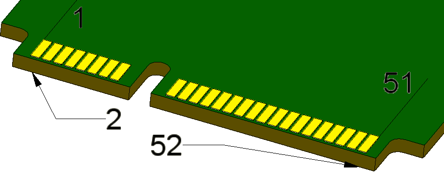
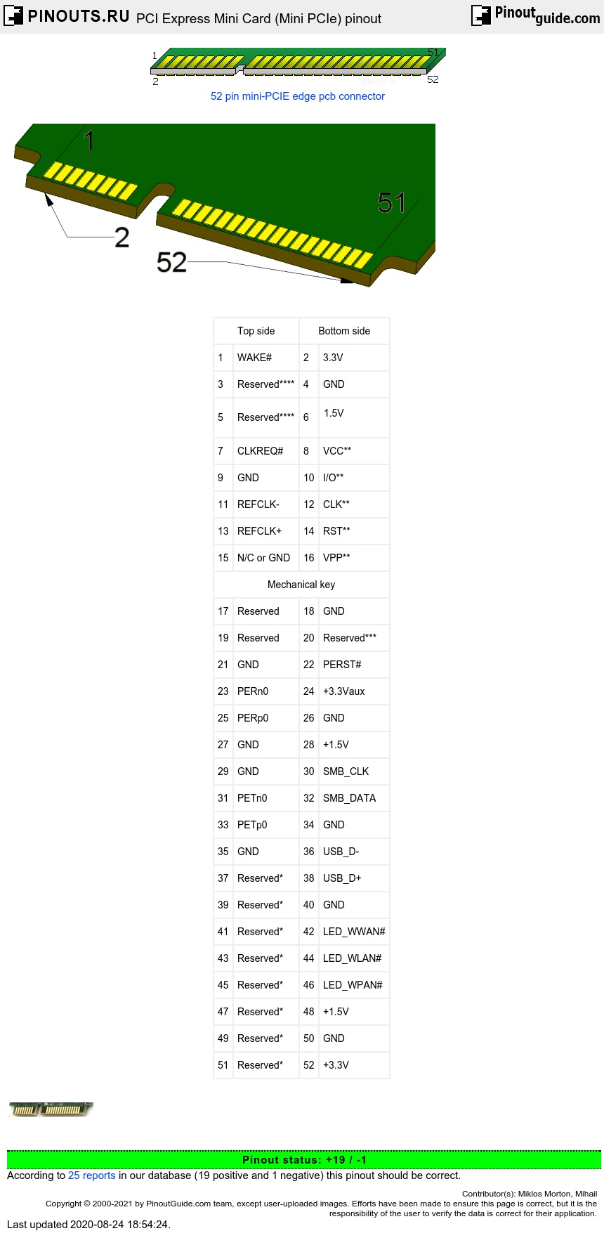
PCI Express Mini Card (also known as Mini PCI Express, Mini PCIe, and Mini PCI-E) is a replacement for the Mini PCI form factor based on PCI Express. It is developed by the PCI-SIG. The host device supports both PCI Express and USB 2.0 connectivity, and each card uses whichever the designer feels most appropriate to the task. Most laptop computers built after 2005 are based on PCI Express and can have several Mini Card slots.
| Top side | Bottom side | ||
| 1 | WAKE# | 2 | 3.3V |
| 3 | Reserved**** | 4 | GND |
| 5 | Reserved**** | 6 |
1.5V |
| 7 | CLKREQ# | 8 | VCC** |
| 9 | GND | 10 | I/O** |
| 11 | REFCLK- | 12 | CLK** |
| 13 | REFCLK+ | 14 | RST** |
| 15 | N/C or GND | 16 | VPP** |
| Mechanical key | |||
| 17 | Reserved | 18 | GND |
| 19 | Reserved | 20 | Reserved*** |
| 21 | GND | 22 | PERST# |
| 23 | PERn0 | 24 | +3.3Vaux |
| 25 | PERp0 | 26 | GND |
| 27 | GND | 28 | +1.5V |
| 29 | GND | 30 | SMB_CLK |
| 31 | PETn0 | 32 | SMB_DATA |
| 33 | PETp0 | 34 | GND |
| 35 | GND | 36 | USB_D- |
| 37 | Reserved* | 38 | USB_D+ |
| 39 | Reserved* | 40 | GND |
| 41 | Reserved* | 42 | LED_WWAN# |
| 43 | Reserved* | 44 | LED_WLAN# |
| 45 | Reserved* | 46 | LED_WPAN# |
| 47 | Reserved* | 48 | +1.5V |
| 49 | Reserved* | 50 | GND |
| 51 | Reserved* | 52 | +3.3V |
*Reserved for future second PCI Express Lane (if needed). Pin 51 has changed to be W_DISABLE2#
**Reserved for future Subscriber Identity Module (SIM) interface (if needed)
***Reserved for future wireless disable signal (if needed)
****Reserved for future wireless coexistence control interface (if needed)


 correct
 incorrect