For models manufactured before 2003
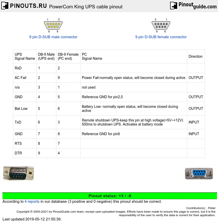
| UPS Signal Name |
DB-9 Male (UPS end) |
DB-9 Female (PC end) |
PC Signal Name |
Direction |
| RxD | 1 | 2 | ||
| AC Fail | 2 | 9 | Power Fail-normally open status, will become closed during active | OUTPUT |
| n/a | 3 | 1 | not used | |
| GND | 4 | 5 | Reference GND for pin2,5 | OUTPUT |
| Bat Low | 5 | 6 | Battery Low- normally open status, will become closed during active |
OUTPUT |
| TxD | 6 | 3 | Remote shutdown UPS-keep this pin at high voltage(+5V~+12V) 500ms to shutdown UPS. Activates at battery mode |
INPUT |
| GND | 7 | 8 | Reference GND for pin6 | INPUT |
| RTS | 8 | 7 | ||
| DTR | 9 | 4 |
AC Fail and Bat Low - normally open (shorted to GND when active).
For models manufactured after 2003 (some pre-2003 models also use this cable)
| UPS Signal Name |
DB-9 Male (UPS end) |
DB-9 Female (PC end) |
PC Signal Name |
Direction |
| n/a | 1 | - | ||
| TxD | 2 | 2,9 | RxD, RI | OUTPUT |
| RxD | 3 | 3 | TxD | INPUT |
| +12V | 4 | 4 | DTR (internally used as source for logical 0 of pin 2) | INPUT |
| GND | 5 | 5 | GND | OUTPUT |
| AC Fail | 6 | - | OUTPUT | |
| -12V | 7 | 7 | RTS (internally used as source for logical 1 of pin 2) | INPUT |
| Bat Low | 8 | - | OUTPUT | |
| n/a | 9 | - |
Note: pins 4 and 7 are used as voltage sources for pin 2 so they should be driven to 0 and 1 accordingly.

 correct
 incorrect