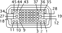
| Pin | Name |
|---|---|
| 1 | Analog audio ground |
| 2 | Audio input shield |
| 3 | Left channel audio input |
| 4 | Right channel audio input |
| 5 | Left channel audio output |
| 6 | Right channel audio output |
| 7 | Reserved |
| 8 | Monitor ID sense line 1 |
| 9 | Monitor ID sense line 2 |
| 10 | Green ground (shield) |
| 11 | Green video output (75 ) |
| 12 | Video input power ground |
| 13 | Power for camera +5 V |
| 14 | Reserved |
| 15 | Reserved |
| 16 | Reserved |
| 17 | Reserved |
| 18 | Monitor ID sense line 3 |
| 19 | S-video input shield |
| 20 | S-video input luminance (Y) |
| 21 | S-video input chroma (C) |
| 22 | Reserved |
| 24 | Reserved |
| 25 | Reserved |
| 26 | Red ground (shield) |
| 27 | Red video output (75 ) |
| 28 | I2C data signal |
| 29 | I2C clock signal |
| 30 | Reserved |
| 31 | Monitor ID |
| 32 | Monitor ID |
| 33 | Vertical sync signal |
| 34 | Composite sync signal |
| 35 | ADB power +5 V |
| 36 | ADB ground |
| 37 | ADB data |
| 38 | Keyboard switch |
| 39 | Reserved |
| 40 | Reserved |
| 41 | Monitor ID |
| 42 | Horizontal sync signal |
| 43 | Video sync ground |
| 44 | Blue ground (shield) |
| 45 | Blue video output (75 ) |
If you did publish instruction for Do-It-Yourself device with this pinout, share the link with us.


 correct
 incorrect