DMX512 data are transmitted over a differential pair using EIA-485 voltage levels. Network wiring consists of a shielded twisted pair, with a characteristic impedance of 120 Ohms, with a termination resistor at the end of the cable furthest from the controller to absorb signal reflections.
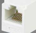
DMX512-A (ANSI E1.11-2008) allows the use of eight-pin modular (8P8C, or RJ-45) connectors for fixed installations where regular plugging and unplugging of equipment is not required. Cat5 cable, commonly used for networking and telecommunications, has been tested by ESTA for use with DMX512A. Also, cables designed for EIA485 typically meet the DMX512 electrical specifications.
| Pin Number |
Pin Name |
Description |
|---|---|---|
| 1 | Data 1+ | Primary Data Link |
| 2 | Data 1- | Primary Data Link |
| 3 | Data 2+ | Optional Secondary Data Link |
| 4 | n/a | |
| 5 | n/a | |
| 6 | Data 2- | Optional Secondary Data Link |
| 7 | Signal Common (0 V) | for Data 1 |
| 8 | Signal Common (0 V) | for Data 2 |
The 8P8C modular connector pinout matches the conductor pairing scheme used by Category 5 (Cat5) twisted pair patch cables. The avoidance of pins 4 and 5 helps to prevent equipment damage, if the cabling is accidentally plugged into a single-line public switched telephone network phone jack.
Color Kinetics DMX
It is important to note that the Color Kinetics wiring is completely different than the ESTA standard.
| Pin Number |
Pin Name |
Description |
|---|---|---|
| 1 | Signal Common (0 V) | for Data 1 |
| 2 | Data 1- | Primary Data Link |
| 3 | Data 1+ | Primary Data Link |
| 4 | n/a | |
| 5 | n/a | |
| 6 | n/a | |
| 7 | n/a | |
| 8 | n/a |
Anolis DMX
It is important to note that the Anolis wiring is completely different than the ESTA standard.
| Pin Number |
Pin Name |
Description |
|---|---|---|
| 1 | n/a | |
| 2 | n/a | |
| 3 | n/a | |
| 4 | n/a | |
| 5 | n/a | |
| 6 | Data 1+ | Primary Data Link |
| 7 | Data 1- | Primary Data Link |
| 8 | Signal Common (0 V) | for Data 1 |
E:Cue DMX
It is important to note that the E:Cue DMX wiring is completely different than the ESTA standard.
| Pin Number |
Pin Name |
Description |
|---|---|---|
| 1 | Data 1- | Primary Data Link |
| 2 | Data 1+ | Primary Data Link |
| 3 | Signal Common (0 V) | for Data 1 |
| 4 | n/a | |
| 5 | n/a | |
| 6 | n/a | |
| 7 | n/a | |
| 8 | n/a |


 correct
 incorrect