NOT sure it's working.
This connection method to obtain very nice picture quality.
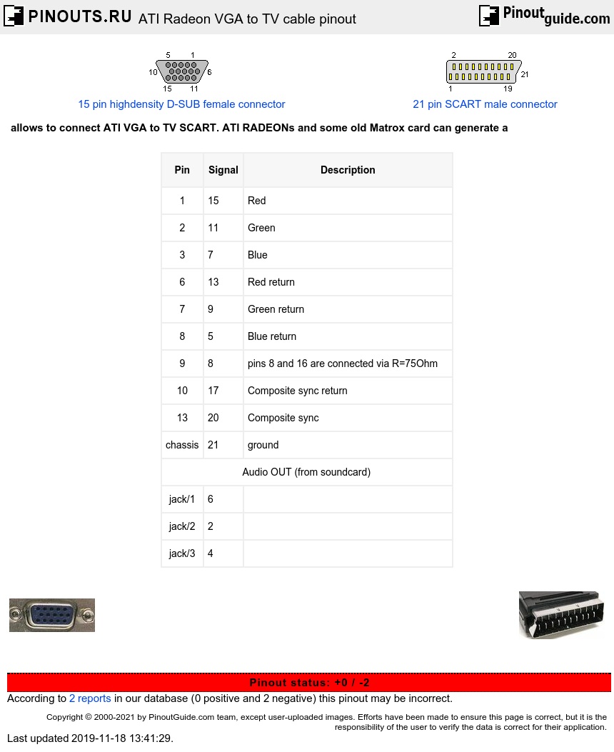
| Pin | Signal | Description |
|---|---|---|
| 1 | 15 | Red |
| 2 | 11 | Green |
| 3 | 7 | Blue |
| 6 | 13 | Red return |
| 7 | 9 | Green return |
| 8 | 5 | Blue return |
| 9 | 8 | pins 8 and 16 are connected via R=75Ohm |
| 10 | 17 | Composite sync return |
| 13 | 20 | Composite sync |
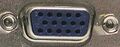
| chassis | 21 | ground |
| Audio OUT (from soundcard) | ||
| jack/1 | 6 | |
| jack/2 | 2 | |
| jack/3 | 4 | |
There are two different wirings used in SCART sockets found on the backs of TVs. The original SCART socket allowed input of either composite or RGB video. Later, as S-video emerged, an evolved SCART socket began to appear that allowed input of either S or composite video. This scheme requires the use of an RGB-capable SCART socket! Some TV have 3 SCART sockets - the first is a black coloured socket that is wired for composite and RGB video and the others are orange coloured sockets that are wired for S and composite video. Older or lower-end sets with one SCART socket are usually wired for composite and RGB video.
 correct
 incorrect