|
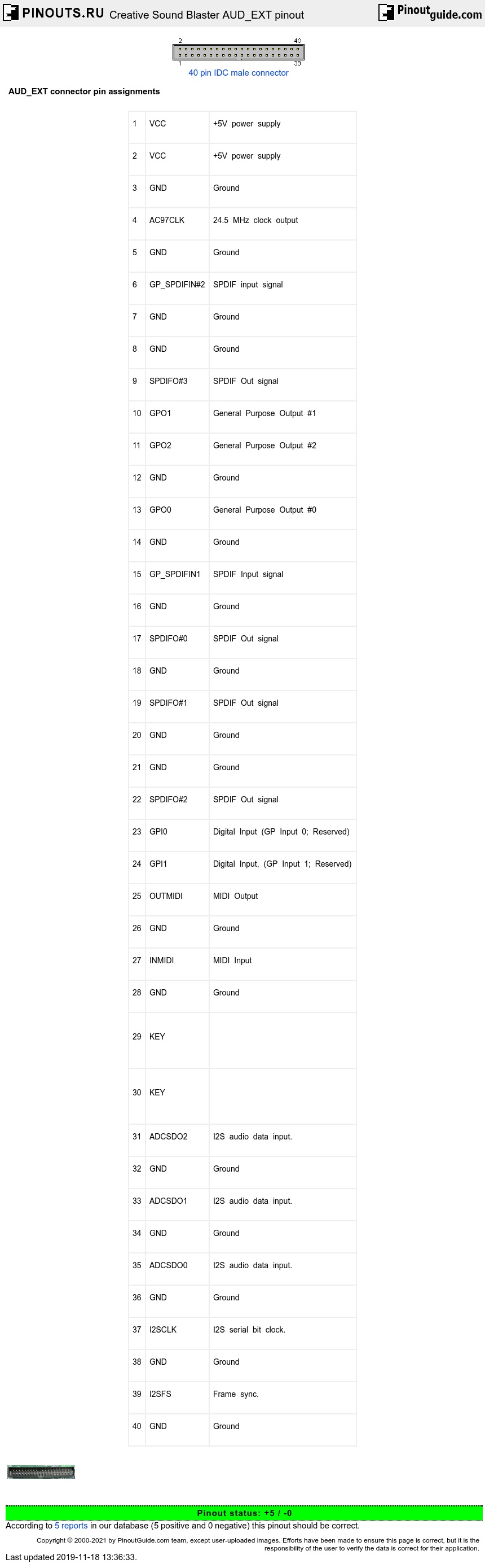
1 |
VCC |
+5V power supply |
|
2 |
VCC |
+5V power supply |
|
3 |
GND |
Ground |
|
4 |
AC97CLK |
24.5 MHz clock output |
|
5 |
GND |
Ground |
|
6 |
GP_SPDIFIN#2 |
SPDIF input signal |
|
7 |
GND |
Ground |
|
8 |
GND |
Ground |
|
9 |
SPDIFO#3 |
SPDIF Out signal |
|
10 |
GPO1 |
General Purpose Output #1 |
|
11 |
GPO2 |
General Purpose Output #2 |
|
12 |
GND |
Ground |
|
13 |
GPO0 |
General Purpose Output #0 |
|
14 |
GND |
Ground |
|
15 |
GP_SPDIFIN1 |
SPDIF Input signal |
|
16 |
GND |
Ground |
|
17 |
SPDIFO#0 |
SPDIF Out signal |
|
18 |
GND |
Ground |
|
19 |
SPDIFO#1 |
SPDIF Out signal |
|
20 |
GND |
Ground |
|
21 |
GND |
Ground |
|
22 |
SPDIFO#2 |
SPDIF Out signal |
|
23 |
GPI0 |
Digital Input (GP Input 0; Reserved) |
|
24 |
GPI1 |
Digital Input, (GP Input 1; Reserved) |
|
25 |
OUTMIDI |
MIDI Output |
|
26 |
GND |
Ground |
|
27 |
INMIDI |
MIDI Input |
|
28 |
GND |
Ground |
|
29 |
KEY |
|
|
30 |
KEY |
|
|
31 |
ADCSDO2 |
I2S audio data input. |
|
32 |
GND |
Ground |
|
33 |
ADCSDO1 |
I2S audio data input. |
|
34 |
GND |
Ground |
|
35 |
ADCSDO0 |
I2S audio data input. |
|
36 |
GND |
Ground |
|
37 |
I2SCLK |
I2S serial bit clock. |
|
38 |
GND |
Ground |
|
39 |
I2SFS |
Frame sync. |
|
40 |
GND |
Ground |
ADC stands for Analog-to-Digital Converter.
 correct
 incorrect