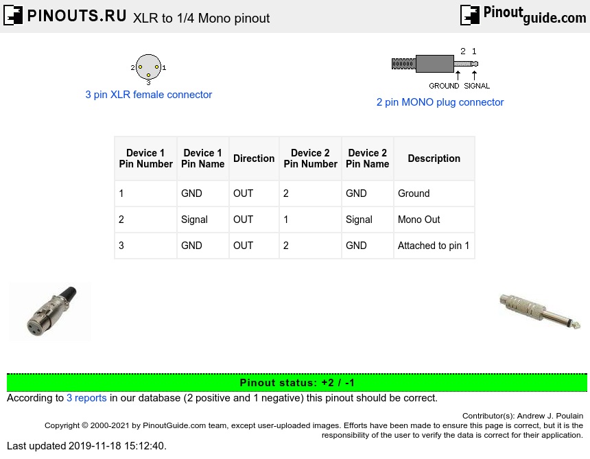
| Device 1 Pin Number |
Device 1 Pin Name |
Direction | Device 2 Pin Number |
Device 2 Pin Name |
Description |
|---|---|---|---|---|---|
| 1 | GND | OUT | 2 | GND | Ground |
| 2 | Signal | OUT | 1 | Signal | Mono Out |
| 3 | GND | OUT | 2 | GND | Attached to pin 1 |
This is correct assuming that the cable used is a two wire (1 conductor and 1 shield) cable. And also only when working with high level signals. If a three wire standard microphone cable is used, the third pin is a signal -. It is to be connected to the sleeve (pin 2-ground) at the 1/4 in. connector.
For a low level signal, note that a standard XLR connection is for a balanced input, which is normally a low impedance input. The 1/4 inch is normally high impedance. A mismatch will cause a sometimes considerable loss of signal at low signal levels normally found in a microphone source. The correct way to connect the two without signal loss is by an impedance matching transformer, or balanced to unbalanced matching device (or more commonly referred to as simply a balun.)


 correct
 incorrect