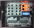
AM/FM connector is white (double)
RFK (rear camera) connector is green
GPS connector is blue
BTE (bluetooth) connecot is curry
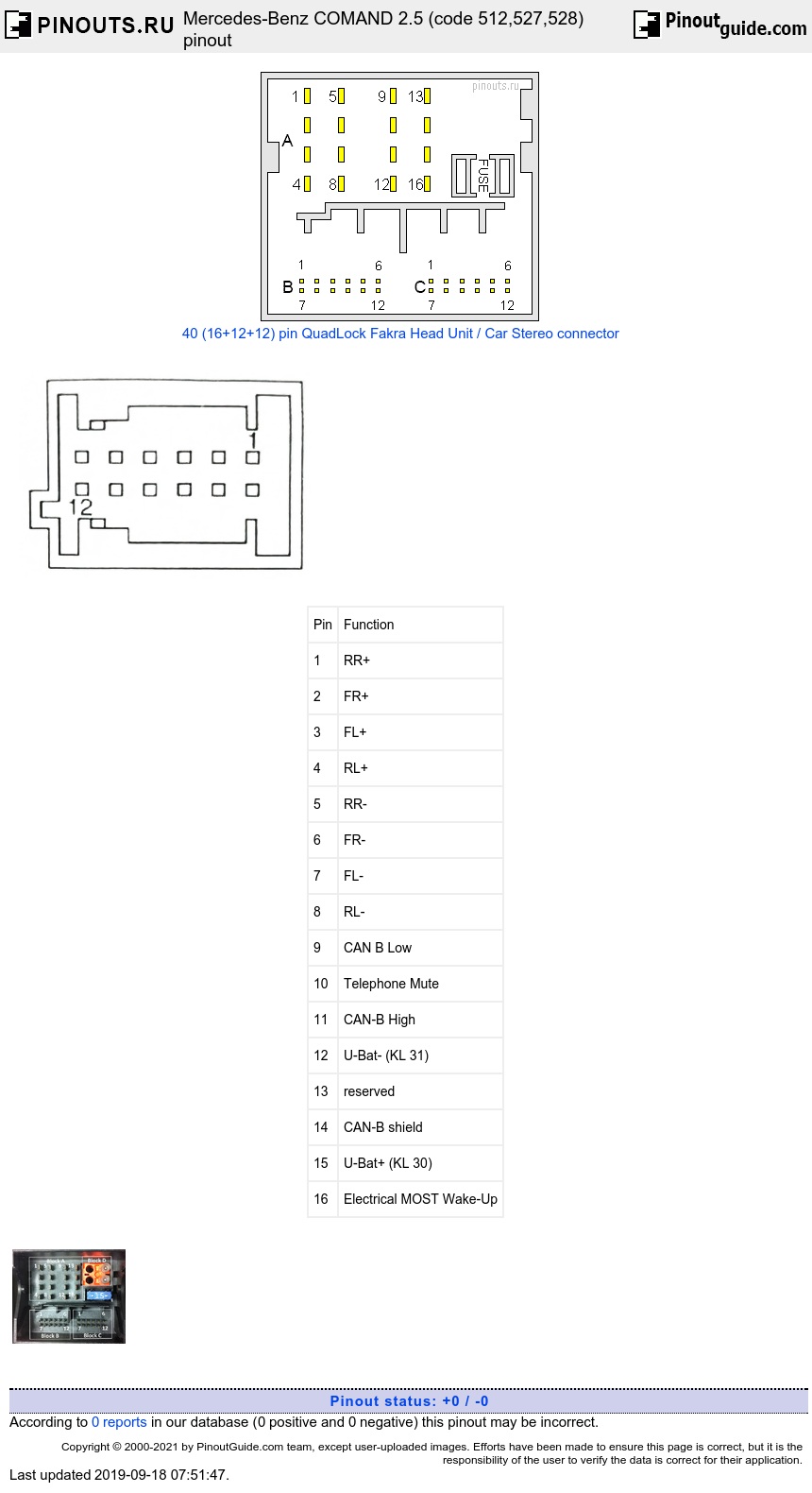
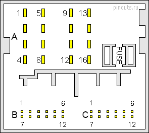
16 pin Block A connector pinout
| Pin | Function |
|---|---|
| 1 | RR+ |
| 2 | FR+ |
| 3 | FL+ |
| 4 | RL+ |
| 5 | RR- |
| 6 | FR- |
| 7 | FL- |
| 8 | RL- |
| 9 | CAN B Low |
| 10 | Telephone Mute |
| 11 | CAN-B High |
| 12 | U-Bat- (KL 31) |
| 13 | reserved |
| 14 | CAN-B shield |
| 15 | U-Bat+ (KL 30) |
| 16 | Electrical MOST Wake-Up |
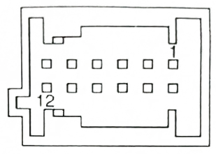
12 pin Block B connector
| 1 | Microphone 1 In + |
|---|---|
| 2 | Microphone 2 In + |
| 3 | Microphone Shield |
| 4 | Microphone Out+ |
| 5 | HU CAN low |
| 6 | HU Can High |
| 7 | Cradke compensator On |
| 8 | reserved |
| 9 | Microphone Ground |
| 10 | Microphone out - |
| 11 | reserved |
| 12 | reserved |
12 pin Block C connector pinout
| 1 | reserved |
|---|---|
| 2 | Ext FAN power supply - |
| 3 | Aux1 shield |
| 4 | Aux1 left |
| 5 | reserved |
| 6 | reserved |
| 7 | Ext FAN diagnosis line |
| 8 | Ext FAN power supply + |
| 9 | Aux1 ground |
| 10 | Aux1 right |
| 11 | reserved |
| 12 | reserved |
Block D (upper right conner)
| 1 | Rx-LWL |
|---|---|
| 2 | Tx-LWL |
12 pin MQS (Japan Only) blue and white Connectors
| Pin Number |
Signal group 3 Code B white connector |
Signal group 4 Code C blue connector |
|---|---|---|
| 1 | ETC Rx | Serial Tx+ |
| 2 | ETC Tx | Seial Tx- |
| 3 | ETC shield | Serial Rx- |
| 4 | VICS Rx | Serial Rx+ |
| 5 | VICS Tx | Voice to Tel (DTR) |
| 6 | VICS shield | Voice from Tel (DCD) |
| 7 | ETC GND | CTS |
| 8 | ETC ON (12V) | RTS |
| 9 | reserved | GND |
| 10 | VICS GND | Power (12V) |
| 11 | VICS power (+5V) | Remote |
| 12 | reserved | Shield Voice Tel |
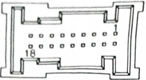
18 pin MQS Group 2 Code A connector pinout
| 1 | Video in CVBS (ECE, USA) or Video in Y (Japan) |
|---|---|
| 2 | Video in Ground (ECE, USA) or Video in Y ground (Japan) |
| 3 | Audio out Ground |
| 4 | Audio out right |
| 5 | Video out CVBS |
| 6 | Video out CVBS shield |
| 7 | reserved |
| 8 | Aux2 ground |
| 9 | Aux2 in left |
| 10 | reserved (ECE, USA) or Video in C (Japan) |
| 11 | reserved (ECE, USA) or Video in C ground (Japan) |
| 12 | Audio out shield |
| 13 | Audio out left |
| 14 | reserved |
| 15 | reserved |
| 16 | reserved |
| 17 | Aux2 shield |
| 18 | Aux2 in right |
Head unit pinout abbreviations
| Pin Notation |
Pin function |
|---|---|
Power pins |
|
| BAT | Battery+ (12V direct from Battery). |
| GND, GROUND | Chassis Ground |
| KL.15 | Ignition powered. +12 V with the ignition key is in the ACC or ON position. |
| iLLUM | Light-on signal or backlight adjustment. +12V supplied to light-on pin of head unit when tail lights ar turned on. |
| ANT OUT | Power for Electric Antenna. Output +12 V (maximum 150 - 300mA) |
Audio pins |
|
| FR+ or RF+ | Front right speaker out |
| FL+ or LF+ | Front left speaker out |
| RR+ | Rear right speaker out |
| LR+ or RL+ | Rear left speaker out |
| FR- or RF-, FL- or LF-, RR-, LR- or RL-, SGND | The corresponding speaker ground |
Misc. pins |
|
| MUTE | This pin is used to silence the audio, earthed by some other external components that is connected to the radio. |
| GAL | This pin is used in some radio equipment to automatically boost up the volume. It needs the output from the speed sensor. |
| CAN-L, CAN-H | CAN on board diagnostic bus |
| K-Line | K-line on board diagnostic bus |

 correct
 incorrect