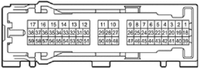
| Pin Num |
W/C | Signal | Details |
|---|---|---|---|
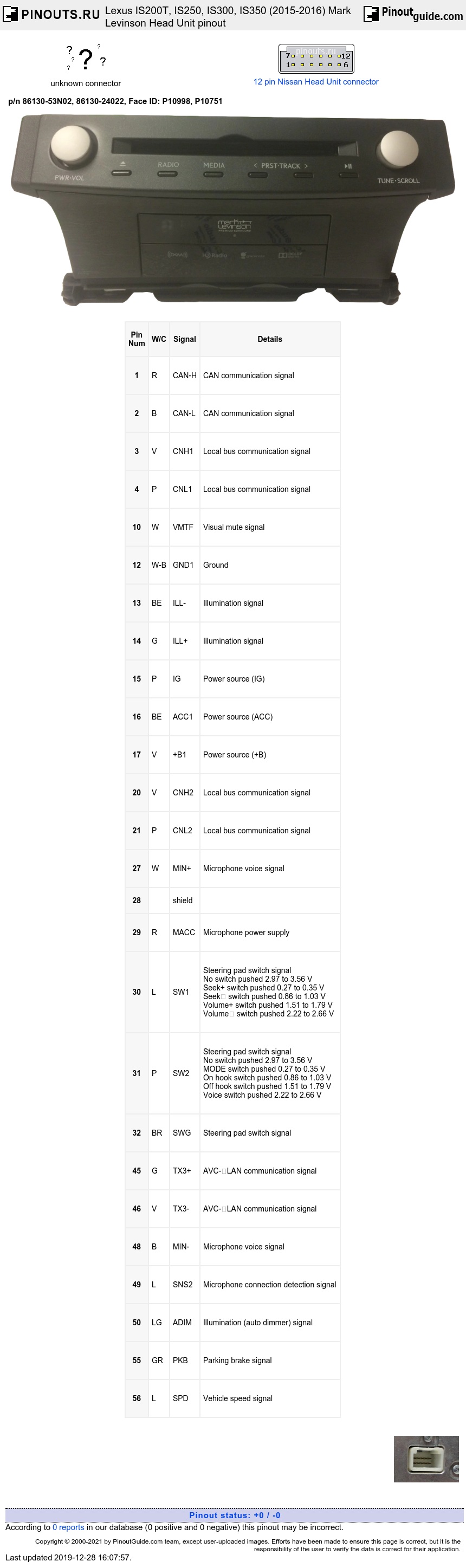
| 1 | R | CAN-H | CAN communication signal |
| 2 | B | CAN-L | CAN communication signal |
| 3 | V | CNH1 | Local bus communication signal |
| 4 | P | CNL1 | Local bus communication signal |
| 10 | W | VMTF | Visual mute signal |
| 12 | W-B | GND1 | Ground |
| 13 | BE | ILL- | Illumination signal |
| 14 | G | ILL+ | Illumination signal |
| 15 | P | IG | Power source (IG) |
| 16 | BE | ACC1 | Power source (ACC) |
| 17 | V | +B1 | Power source (+B) |
| 20 | V | CNH2 | Local bus communication signal |
| 21 | P | CNL2 | Local bus communication signal |
| 27 | W | MIN+ | Microphone voice signal |
| 28 | shield | ||
| 29 | R | MACC | Microphone power supply |
| 30 | L | SW1 | Steering pad switch signal No switch pushed 2.97 to 3.56 V Seek+ switch pushed 0.27 to 0.35 V Seek switch pushed 0.86 to 1.03 V Volume+ switch pushed 1.51 to 1.79 V Volume switch pushed 2.22 to 2.66 V |
| 31 | P | SW2 | Steering pad switch signal No switch pushed 2.97 to 3.56 V MODE switch pushed 0.27 to 0.35 V On hook switch pushed 0.86 to 1.03 V Off hook switch pushed 1.51 to 1.79 V Voice switch pushed 2.22 to 2.66 V |
| 32 | BR | SWG | Steering pad switch signal |
| 45 | G | TX3+ | AVC-LAN communication signal |
| 46 | V | TX3- | AVC-LAN communication signal |
| 48 | B | MIN- | Microphone voice signal |
| 49 | L | SNS2 | Microphone connection detection signal |
| 50 | LG | ADIM | Illumination (auto dimmer) signal |
| 55 | GR | PKB | Parking brake signal |
| 56 | L | SPD | Vehicle speed signal |
W/C stands for Wire Color. Those are for IS200T and are very dependent on model and model year.
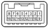
| Pin Num |
W/C | Signal | Details |
|---|---|---|---|
| 5 | shield | ||
| 6 | P | VV+ | Video signal |
| 7 | W | VAR+ | Sound signal (Right) |
| 8 | B | VAL+ | Sound signal (Left) |
| 13 | shield | ||
| 14 | L | VV- | Video signal ground |
| 15 | R | VA- | Sound signal ground |
| 16 | P | ADPG | External device connection detection signal |
W/C stands for Wire Color. Those are for IS200T and are very dependent on model and model year.
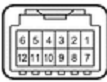
| Pin Num |
W/C | Signal | Detaild |
|---|---|---|---|
| 11 | BE | GND2 | Ground |
| 12 | G | ACC | Power source (ACC) |
W/C stands for Wire Color. Those are for IS200T and are very dependent on model and model year.
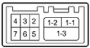
| Pin Num |
W/C | Pin | Signal |
|---|---|---|---|
| 1-1 | B | USB- | USB communication line |
| 1-2 | B | USB+ | USB communication line |
| 1-3 | B | USBS | Shield ground |
| 2 | W | USBG | ground |
| 3 | W | VOT+ | Sent voice signal |
| 4 | W | USBV | DCM (telematics transceiver) power supply (4.75-5.25V) |
| 5 | R | VOT- | Sent voice signal |
| 6 | B | VOR- | Receive voice signal |
| 7 | G | VOR+ | Receive voice signal |
W/C stands for Wire Color. Those are for IS200T and are very dependent on model and model year.
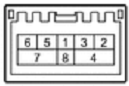
| Pin Num |
W/C | Signal | Details |
|---|---|---|---|
| 1 | W | WUO | MOST communication wakeup signal |
| 2 | B | MI+ | MOST communication signal |
| 3 | B | MI- | MOST communication signal |
| 4 | shield | ||
| 5 | B | MO+ | MOST communication signal |
| 6 | B | MO- | MOST communication signal |
| 7 | shield | SLDO |
W/C stands for Wire Color. Those are for IS200T and are very dependent on model and model year.

| Pin Num |
Pin | Signal |
|---|---|---|
| 1 | USV1 | Power source |
| 2 | US1- | Data signal |
| 3 | US1+ | Data signal |
| 4 | USGD1 | Ground |
| 5 | USG1 | Shield ground |
W/C stands for Wire Color. Those are for IS200T and are very dependent on model and model year.
 correct
 incorrect