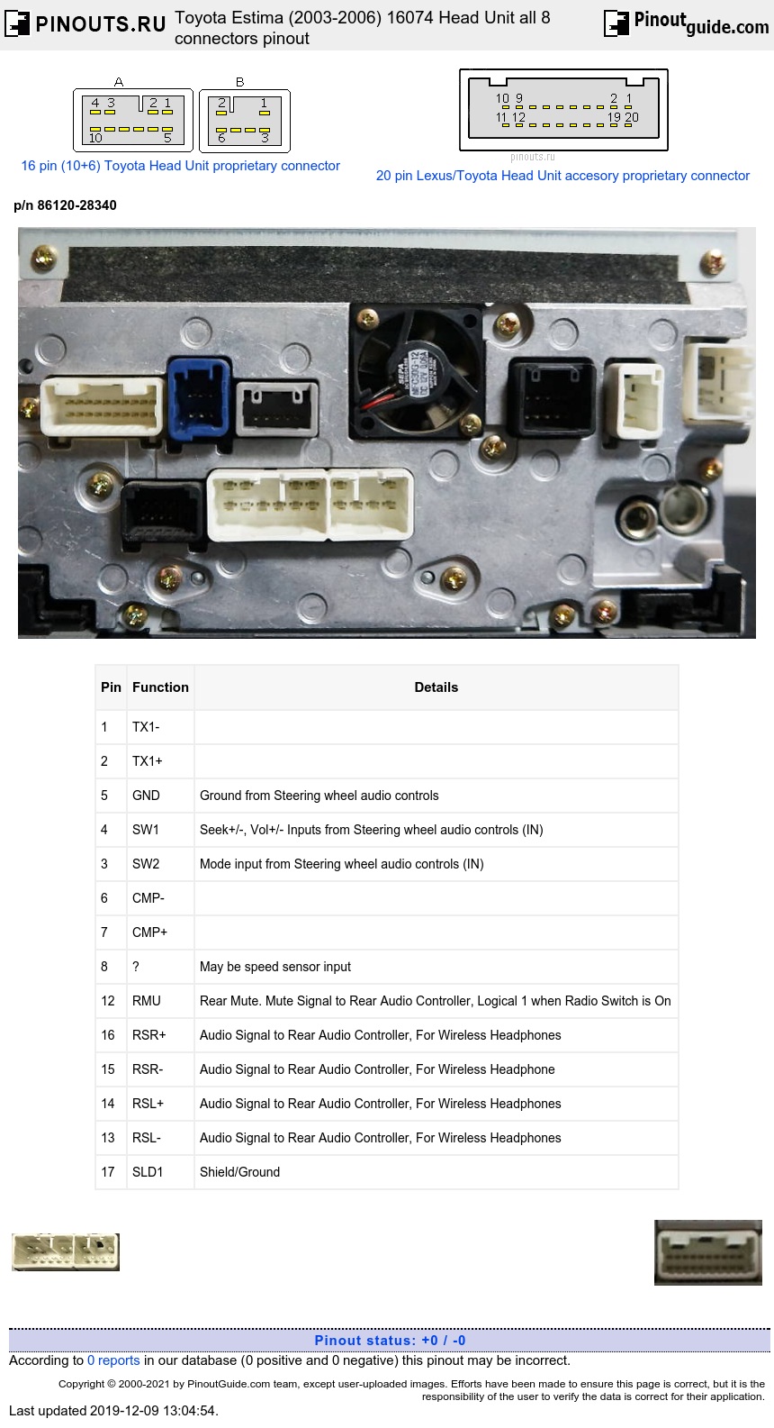
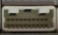
20-Pin Rear Controller Audio, Steering Wheel Controls Connector
Check Pin Numbering! Part number of connector is 90980-12259
| Pin | Function | Details |
|---|---|---|
| 1 | TX1- | |
| 2 | TX1+ | |
| 5 | GND | Ground from Steering wheel audio controls |
| 4 | SW1 | Seek+/-, Vol+/- Inputs from Steering wheel audio controls (IN) |
| 3 | SW2 | Mode input from Steering wheel audio controls (IN) |
| 6 | CMP- | |
| 7 | CMP+ | |
| 8 | ? | May be speed sensor input |
| 12 | RMU | Rear Mute. Mute Signal to Rear Audio Controller, Logical 1 when Radio Switch is On |
| 16 | RSR+ | Audio Signal to Rear Audio Controller, For Wireless Headphones |
| 15 | RSR- | Audio Signal to Rear Audio Controller, For Wireless Headphone |
| 14 | RSL+ | Audio Signal to Rear Audio Controller, For Wireless Headphones |
| 13 | RSL- | Audio Signal to Rear Audio Controller, For Wireless Headphones |
| 17 | SLD1 | Shield/Ground |
6-Pin DVD Changer Video Blue Connector
Part number of connector is 90980-12209
| Pin | Function | Details |
|---|---|---|
| 1 | V+ | |
| 3 | AR+ | |
| 4 | AL+ | |
| 5 | A- | |
| 6 | ADPG | Signal Ground |
5-Pin Sensor signals Gray Connector

Part number of connector is 90980-11909, p/n of plug is 90980-11920
| Pin | Function | |
|---|---|---|
| 1 | PKB | Parking Break. This signal is grounded when parking break switch is closed. Floats otherwise (Input) |
| 2 | IG | |
| 3 | SPD | Generated from the Speedometer. Most likely this is the Vehicle speed sensor pulse line (Input) |
10-Pin Video & Communications Black Connector
Part number of connector is 90980-11922, p/n of plug is 90980-11923
| Pin | Function | Details |
|---|---|---|
| 1 | VR | Grounded when Ignition Switch is Off |
| 2 | R | Red VGA (Input) |
| 3 | B | Blue VGA (Input) |
| 5 | TX+ | AVC-LAN |
| 6 | VG | Ground |
| 7 | G | Green VGA (Input) |
| 8 | SYNC | Probably VSync |
| 10 | TX- | AVC-LAN |
4-Pin Reverse Camera Video and Power Connector
Part number of connector is 90980-12211
| Pin | Function | Details |
|---|---|---|
| 1 | V+ | Positive Voltage Terminal?? Referred to as B-Eye on Schematics, Probably a composite video signal |
| 2 | CA+ | Output, Camera power? |
| 3 | V- |
Negative Voltage Terminal |
| 4 | GND | Ground |
5-Pin TV Antenna Connector
| Pin | Function |
|---|---|
| 1 | DIV2 out |
| 2 | DIV1 out |
| 3 | TV+ out |
| 4 | DGND |
| 5 | TV ANT |
12-Pin Rear audio controller, DVD Changer Audio Black Connector
Numbering is wrong??
| Pin | Function | Details |
|---|---|---|
| 1 | SLD | Shield/Ground |
| 2 | R+ | Right Audio Input Positive |
| 3 | R- | Right Audio Input Negative |
| 4 | L+ | Left Audio Input Positive |
| 5 | L- | Left Audio Input Negative |
| 6 | Mute | Logical 1 when Radio Switch is On |
| 7 | GND | Ground |
| 9 | TX+ | Transmission+ |
| 10 | TX- | Transmission- |
| 11 | ACC+B | +12V when key is in ACC/AUX position |
| 12 | BU+B | Battery +12V |
Part number of 10 pin connector is 90980-11781 or 90980-10801, p/n of plug is 90980-10881
Part number of 6 pin connector is 90980-10996 or 90980-10796
| Pin | Function | Details |
|---|---|---|
| 1 | FR+ | |
| 2 | FL+ | |
| 3 | ACC+ | |
| 4 | BAT+ | |
| 5 | FR- | |
| 6 | FL- | |
| 7 | GND | |
| 8 | ANT+ | |
| 10 | ILL+ | |
| 11 | RR+ | |
| 12 | RL+ | |
| 13 | RR- | |
| 14 | CMP- | |
| 15 | CMP+ | |
| 16 | RL- |
 correct
 incorrect