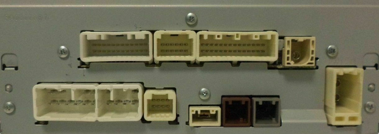
p/n 868040C100
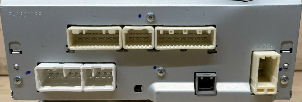
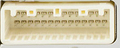
J137 / J138
| Pin Num |
Signal - Ground | wire color |
Option | Description |
|---|---|---|---|---|
| A1 | J137-1 (FR+) - J137-7 (GND1) |
BE - W-B | 7 or 9 Speakers | Sound signal (Front right) |
| G - W-B | 4 or 6 Speakers | |||
| A2 | J137-2 (FL+) -J137-7 (GND1) | B - W-B | Sound signal (Front left) | |
| A3 | J137-3 (ACC1) -J137-7 (GND1) | GR - W-B | Power source (ACC). 11-14V when ignition switch ACC | |
| A4 | J137-4 (+B1) -J137-7 (GND1) | V - W-B | Power source (+B) 11-14V constant. | |
| A5 | J137-5 (FR-) -J137-7 (GND1) | LG - W-B | 7 or 9 Speakers | Sound signal (Front right) |
| R - W-B | 4 or 6 Speakers | |||
| A6 | J137-6 (FL-) -J137-7 (GND1) | V - W-B | 7 or 9 Speakers | Sound signal (Front left |
| BE - W-B | 4 or 6 Speakers | |||
| A7 | J137-7 (GND1) - Body ground | W-B - Body ground | Ground | |
| A9 | J137-9 (AMP) -J137-7 (GND1) | G - W-B | 7 or 9 Speakers | Power source of stereo component amplifier (11-14V) |
| A10 | J137-10 (ILL+) -J137-7 (GND1) | SB - W-B | Illumination signal 11-14V when Light control switch in tailor head position. | |
| B1 | J138-1 (RR+) - J137-7 (GND1) | BR -W-B | except 4 Speakers | Sound signal (Rear right) |
| B2 | J138-2 (RL+) -J137-7 (GND1) | Y - W-B | except 4 Speakers | Sound signal (Rear left) |
| B3 | J138-3 (RR-) - J137-7 (GND1) | V - W-B | 7 or 9 Speakers | Sound signal (Rear right) |
| LG - W-B | 6 Speakers | |||
| B5 | J138-5 (ILL-) - J137-7 (GND1) | SB - W-B | Illumination signal | Pulse generation when Headlight dimmer switch assembly in tail or head position |
| B6 | J138-6 (RL-) -J137-7 (GND1) | P - W-B | 7 or 9 Speakers | Sound signal (Rear left) |
| B - W-B | 6 Speakers |
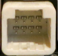
J139 (28 pin)
| Pin Num |
Signal - Ground | wire color |
Option | Description |
|---|---|---|---|---|
| 1 | J139-1 (IG) - J137-7 (GND1) | P - W-B | Power source (IG). 11-14V when Ignition switch ON. | |
| 2 | J139-2 (REV) - J137-7 (GND1) | Y - W-B | Reverse signal. | |
| 4 | J139-4 (MACC) -J137-7 (GND1) | L- W-B | Microphone power supply. 4 to 6V when Ignition switch ACC | |
| 5 | J139-5 (MIN+) -J137-7 (GND1) | B - W-B | Microphone voice signal | |
| 6 | J139-6 (SNS2) -J137-7 (GND1) | LG - W-B | Microphone connection detection signal (always <1V) | |
| 9 | J139-9 (CANH) | LG | CAN communication signal | |
| 10 | J139-10 (CANL) | W | CAN communication signal | |
| 11 | J139-11 (AGND)- Body ground | Shield Ground | ||
| 15 | J139-15 (PKB) -J137-7 (GND1 | R - W-B | Parking W-Bake signal | |
| 17 | J139-17 (SPD) -J137-7 (GND1) | W - W-B | Vehicle speed signal from combination meterassembly | |
| 18 | J139-18 (SGND)- J137-7 (GND1) | Shield - W-B | Shield Ground | |
| 19 | J139-19 (MIN-) -Body ground | Y - Body ground | Microphone voice signal | |
| 21 | J139-21 (SW1) -J139-23(SWG) | G - Y | w/ Steering Pad Switch | Steering pad switch signal No switch pushed 2.97 to 3.56 V Up switch pushed 0.27 to 0.35 V Down switch pushed 0.86 to 1.03 V Volume+ switch pushed 1.51 to 1.79 V Volume- switch pushed 2.22 to 2.66 V |
| 22 | J139-22 (SW2) -J139-23(SWG) | GR - Y | w/ Steering Pad Switch | Steering pad switch signal No switch pushed 2.97 to 3.56 V MODE/HOLD switch pushed 0.27 to 0.35 V On hook switch pushed 0.86 to 1.03 V Off hook switch pushed 1.51 to 1.79 V Voice switch pushed 2.22 to 2.66 V |
| 23 | J139-23 (SWG) - Body ground | Y - Body ground | w/ Steering Pad Switch | Steering pad switch signal ground |
| 24 | J139-24 (SW3) -J139-23 (SWG) | L - Y | Steering pad switch signal No switch pushed 2.97 to 3.56 V Enter switch pushed 0.27 to 0.35 V Back switch pushed 0.86 to 1.03 V Right switch pushed 1.51 to 1.79 V Left switch pushed 2.22 to 2.66 V |
|
| 25 | 139-25 (ADPG)- J137-7 (GND1) | SB - W-B | External device connection detection signal. <1V when connected, otherwise 2-3V | |
| 26 | J139-26 (VAR+)- J139-27 (VA-) | B - Y | Sound signal (Right) External device playing audio (When stereo jack used) | |
| 27 | J139-27 (VA-) -J137-7 (GND1) | Y - W-B | Sound signal ground | |
| 28 | 139-28 (VAL+) -J139-27 (VA-) | L - Y | Sound signal (Left). External device playing audio (When stereo jack used) |
L2 8-pin connector
| Pin Num |
Signal - Ground | wire color |
Option | Description |
|---|---|---|---|---|
| 3 | L2-3 (ACC2) -J137-7 (GND1) | Y - W-B | w/ SDARS System | Power source (ACC) |
| 4 | L2-4 (+B2) -J137-7 (GND1)* | R - W-B | w/ SDARS System | Power source (+B) |
| 8 | L2-8 (GND2) - Body ground* | B - Body ground | w/ SDARS System | Ground |
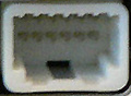
J122 5-pin
| Pin Num |
Signal - Ground | wire color |
Option | Description |
|---|---|---|---|---|
| 1 | J122-1 (USV1) | Power source | ||
| 2 | J122-2 (US1-) | Data signal | ||
| 3 | J122-3 (US1+) | Data signal | ||
| 4 | J122-4 (USD1) | Ground | ||
| 5 | J122-5 (USG1) | Shield Ground |
K5 5-pin
| Pin Num |
Signal - Ground | wire color |
Option | Description |
|---|---|---|---|---|
| 1 | K5-1 (USV4) | w/ SDARS System | Power source | |
| 2 | K5-2 (USV4-) | w/ SDARS System | Data signal | |
| 3 | K5-3 (USV4+) | w/ SDARS System | Data signal | |
| 4 | K5-4 (USGD4) | w/ SDARS System | Ground | |
| 5 | K5-5 (USG4) | w/ SDARS System | Shield Ground |
Omitted pins are Not Connected.
 correct
 incorrect