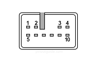
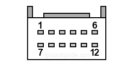
| Pin Num |
Wire Color |
Signal |
|---|---|---|
| 1 | LG | FR(+) |
| 2 | P | FL(+) |
| 3 | GR | ACC |
| 4 | SB | +B |
| 5 | L | FR(-) |
| 6 | V | FL(-) |
| 7 | BR | GND |
| 9 | SB | AMP |
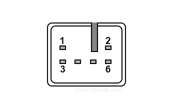
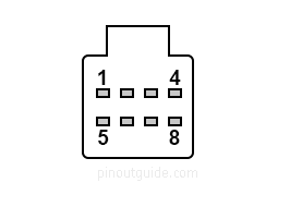
| Pin Num |
Wire Color |
Signal |
|---|---|---|
| 1 | R | RR(+) |
| 2 | B | RL(+) |
| 3 | W | RR(-) |
| 6 | Y | RL(-) |
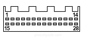
| Pin Num |
Wire Color |
Signal |
|---|---|---|
| 1 | LG | IG |
| 4 | R | MACC |
| 5 | B | MIN+ |
| 6 | GR | SNS2 |
| 9 | BE | CAN-H |
| 10 | W | CAN-L |
| 11 | shield | AGND VA shield |
| 15 | P | PKB (after 2014MY) |
| 17 | V | SPD |
| 18 | shield | SGND MIN, MACC shield |
| 19 | W | MIN- |
| 21 | L | SW1 |
| 22 | P | SW2 |
| 23 | R | SWG |
| 25 | R | ADPG |
| 26 | R | VAR+ |
| 27 | W | VA- |
| 28 | B | VAL+ |
to extension module (before 2014 MY)
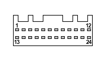
| Pin Num |
Wire Color |
Signal |
|---|---|---|
| 1 | B | +B |
| 2 | G | SPDO |
| 5 | L | REVO |
| 6 | Y | VSYN |
| 7 | P | HSYN |
| 8 | LG | AGND |
| 10 | W | B |
| 11 | R | G |
| 12 | V | R |
| 13 | P | ACC2 |
| 14 | W-B | GND |
| 19 | R | MIC+ |
| 20 | V | MIC- |
| 22 | Y | VOI+ |
| 23 | W | VOI- |
to extension module (before 2014 MY)
| Pin Num |
Wire Color |
Signal |
|---|---|---|
| 2 | L | CDR+ |
| 3 | LG | CDR- |
| 4 | BR | CDL+ |
| 5 | G | CDL- |
| 6 | B | MUTE |
| 9 | BR | TX+ |
| 10 | W-B | TX- |
to extension module (before 2014 MY)
| Pin Num |
Wire Color |
Signal |
|---|---|---|
| 1 | B | SLD4 |
| 2 | B | SPDO |
| 3 | B | ACC |
| 4 | W | +B |
| 5 | B | MIC+ |
| 6 | B | MIC- |
| 8 | W | GND |
after 2014 MY
| Pin Num |
Wire Color |
Signal |
|---|---|---|
| 3 | P | CNH1 after 2017MY |
| 4 | W | CNL1 after 2017MY |
| 11 | R | CA+ |
| 12 | B | V+ |
| 23 | shield | CGND |
| 24 | W | V- |
16-pin connector
before 2014MY
| Pin Num |
Wire Color |
Signal |
|---|---|---|
| 6 | P | PKB |
| 7 | R | CA+ |
| 8 | B | V+ |
| 15 | shield | CGND |
| 16 | W | V- |
Omitted pins are Not Connected.
Toyota Signals
| Signal | Details |
|---|---|
| FR(+), FR(-) | Sound signal output (Front Right) |
| FL(+), FL(-) | Sound signal output (Front Left) |
| RR(+), RR(-) | Sound signal output (Rear Right) |
| RL(+), RL(-) | Sound signal output (Rear Left) |
| CNH, CNL | Local bus communication signal |
| REV | Reverse signal |
| PKB | Parking brake signal. This signal is grounded when parking break switch is closed. Floats otherwise |
| SPD | Vehicle speed signal. Generated from the Speedometer. Most likely this is the Vehicle speed sensor pulse line. |
| ACC | Power source (ACC). 11-14V when ignition switch ACC |
| B+, +B | Power source (Battery). 11-14V constant. |
| CA+ | Rear camera power supply |
| V+, V- | Rear camera display signal (composite?) |
| MACC | Microphone power supply (4-6V) |
| MIN+, MIN- | Microphone voice signal input |
| SNS, SNS2 | Microphone connection detection signal (always <1V) |
| TX1+, TX1- | AVC-LAN communication signal (usually amplifier communication) |
| SW1, SW2, SW3 | Steering pad switch signal (SWG - signal ground) |
| ADPG | External device connection detection signal. <1V when connected, otherwise 2-3V |
| VAR(+), VAL(+) | Sound signal input (Right, Left). External device playing audio (When stereo jack used) |
| ARI, ALI | Stereo Jack sound signal input (Right, Left). External device playing audio (When stereo jack used) |
Toyota Wiring Color Codes
| B=Black | W=White | BR=Brown |
| L=Blue | V=Violet | SB=Sky Blue |
| R=Red | G=Green | LG=Light Green |
| P=Pink | Y=Yellow | GR=Gray |
| O=Orange | BE=Beige | DG=Dark Gray |
 correct
 incorrect